![<?echo $_SERVER['SERVER_NAME'];?>](/template/twentyseventeen/skin/images/header.jpg)
Abstract: A design scheme for projector lifting control based on Atmega8 and Stm32F101 dual processor is proposed, and its circuit composition, function and software flow are introduced. Among them Atmega8 is responsible for data collection, Stm32F101 realizes the control of the motor, and the processors communicate through the I2C bus. The system is controlled by infrared remote control or external key input device, and it can also be controlled online by PC. The test verifies that the design scheme is correct and effective, and the fixed point accuracy meets the practical requirements.
1 Introduction
The projector lifting control system is composed of Atmega8 data acquisition circuit, Stm32F101 control circuit, motor rotation number detection module, infrared remote control receiving and sending module, external key module and external anti-interference circuit. The goal is to control the lifting of multimedia devices such as projectors. In the scheme, the upper limit of the highest point and the lowest point of the projector can be set at any time. After the setting, no matter where the projector is, the highest point can be reached when the up button is pressed, and the lowest point can be reached when the down button is pressed. Click and stop the movement when you press the stop button. The operation mode combining coarse adjustment and fine adjustment is adopted. The projector continuously rises or falls when the operation button is pressed for 3 seconds, and stops when the hand is released. It is mainly used for coarse adjustment; when the operation button is short pressed, the projector automatically stops after a certain distance. For fine-tuning. After setting, use the save key to save the setting. If the setting is not saved, the set point is invalid. The infrared remote controller can set the operating parameters, and can also be controlled by lifting.
2 Basic control methods
The key of the control system is that the projector can be raised and lowered to any position. The lifting process is achieved by the motor. The linear distance of the lift corresponds to the number of rotations of the motor. The control of the number of rotations of the motor is also achieved. control. The technical breakthrough of this solution is to convert the precise linear distance control into the control of the number of motor rotations. One rotation of the motor corresponds to a linear distance of one millimeter of lift. The linear distance control accuracy of this solution is one millimeter, that is, the motor is rotated A circle of digital controls. Two infrared sensors are used in the motor control module to collect the number of rotations and the direction of rotation of the motor. The Atmega8 two I / O pins collect the signal output from the sensor. The level of the pin combined signal changes to 00, 10, 11 , 01 (clockwise) or 00, 01, 11, 10 (counterclockwise). This article uses the motor _state structure to represent the state of the motor. The meaning of each element in the structure is as follows:
You can know whether the motor is rotating by comparing the values ​​of the first two elements of the structure; by comparing the 3 and 4 elements, you can accurately locate the projection position. When they are equal, an interrupt is generated and the motor is ordered to stop rotating; 00 to 10, motor _ bit _ L 0th position one, 10 to 11, first position one, 11 to 01, second position one, 01 to 00, third position one, so when the lower 4 bits When all 1, the motor rotates one turn counterclockwise, and one clockwise rotation is represented by motor _ bit _ R.
3 Control system hardware design
The control system is generally divided into two parts: signal acquisition and motor control.
For example, Atmega8 on the right side of the system block diagram is mainly used for infrared sensor signal level acquisition. When the Stm32F101 controls the motor to move up and down, the motor turns detection circuit will input a signal to the Atmega8 through the infrared sensor, thereby judging the operation of the motor. On the left is the lifting part of the Stm32F101 control motor. Commands can be input by infrared remote control or by pressing keys after connecting with PC. When the Atmega8 collects the infrared sensor signal level, it can communicate with the Stm32F101 through the I2C bus. When the projector reaches the destination point, an interrupt signal is sent to cause the Stm32F101 to generate an interrupt and process related operations. As shown in the figure, the internal data of two E2PROMs can be easily read and written through the serial port. The power-down saving module uses CAT24WC16, even if there is a sudden power failure during operation, it can automatically save the state parameters of the motor at the time of power failure, that is, save the motor _state structure variable.
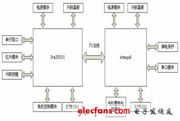
Figure 1 Controller system hardware structure diagram
3.1 Motor turns detection unit
This unit is in an important position in the entire system. A semicircular iron piece is sleeved on one end of the motor rotating shaft and placed between the transmitting end and the receiving end of the infrared sensor. When the motor rotates, the iron piece rotates with it. There are two infrared sensors in the lap detection unit, each of which consists of a transmitter and a receiver. When the transmitter and receiver are blocked by a semi-circular iron plate, the output signal is low level 0, and when not blocked, the output signal is high level 1. Because it is a semi-circular iron plate, with the continuous rotation of the motor, Atmega8 two pins Receive the infrared sensor signal and continuously detect the input level of the two pins. When the input level of the two pins does not change, the motor is not rotating. When the change state is 00, 10, 11, 01 or 00, 01, 11, 10, it indicates that the motor is rotating. The state sequence reflects the motor rotating clockwise or counterclockwise.
3.2 Motor control module
Figure 2 is the hardware schematic diagram of Stm32F101's motor control.
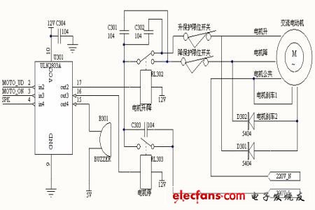
Figure 2 Motor control hardware structure diagram.
In the picture, ULN2803A is a Darlington driving device, controlled by Stm32F101, MOTO_UD, MOTO_ON, SPK is directly connected to Stm32F101, their functions are to control the motor up and down, control whether the motor works or stops, and control the buzzer to stop. When the relay RL303 works, the motor works under 220V AC, otherwise it stops working. When the relay RL302 is normally open, it is known from the figure that it is to control the motor up operation, otherwise the normally closed is to operate the motor down operation. In order to improve the safety of the motor, the lifting protection is also adopted. As shown in the figure, there are two limit switches connected, which are the rising and falling limit protection, that is, the limit switch is disconnected when the limit point is reached, causing the motor to stop working. To the role of the protection circuit.
Power Breadboard,Breadboard Power Supply,Breadboard Power Supply Module,Breadboard Power Module
Cixi Zhongyi Electronics Factory , https://www.zypcbboards.com