![<?echo $_SERVER['SERVER_NAME'];?>](/template/twentyseventeen/skin/images/header.jpg)
The test of the engine temperature field refers to the measurement of the wall surface temperature and the hot end components of the high temperature gas turbine engine combustion chamber. The length of service life of the hot end components of the engine is closely related to the uniform distribution of the temperature field of the hot end components, so the engine temperature field must be accurately tested.
1 Research status
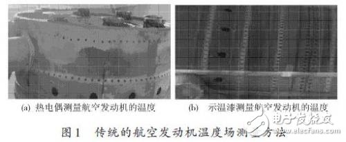
At present, domestic engine production and repair companies test the temperature field of some parts of the engine mainly by direct contact method and manual interpretation method. The direct contact method uses a thermocouple to directly test the temperature of the engine components, as shown in Figure 1(a). However, with this method, the measurement error is large, and only the temperature of some points can be measured, and the measurement of the entire temperature field cannot be realized. Manual interpretation means that the engine production and repair company uses the color temperature characteristics of the temperature paint to indirectly manually interpret the temperature of the engine components, as shown in Figure 1(b). At present, most engine manufacturers use temperature-sensitive paint to indirectly measure the temperature field of engine components. Temperature paint is a temperature sensor that can display different colors in different temperature ranges and apply it to the surface of engine test pieces. The temperature is judged according to the color of the paint on the surface of the test piece.
Using temperature paint to measure the temperature field of the hot end part of the engine has the advantages of large measuring area, wide temperature range, convenient use, simple operation, and no damage to the surface shape of the object, so it can be widely used, but this method is easy to use. The influence of ambient light has the disadvantages of large error and low efficiency. In order to improve the test accuracy, test efficiency and robustness of the engine temperature field, this paper presents a multi-sensor image fusion engine temperature field test system for the first time.
2 system overall design
2.1 Working principle
The entire engine temperature field test system consists of the light source, engine temperature field test components, lens, CCD image sensor, image acquisition card, image fusion processing and temperature recognition computer. The function of the light source is to provide sufficient light for image acquisition in a dim environment or under special illumination requiring separate light; the role of the lens is to ensure that the image sensor can acquire a target image of appropriate size and high definition through its own adjustment; The image sensor converts the image into a signal by CCD or CMOS sensor. The image capture card is mainly used to collect and transmit the target image acquired by the image sensor to the computer image processing system. The computer performs image fusion and processing on the captured image. And temperature identification. The overall block diagram of the entire engine temperature field test system is shown in Figure 2.
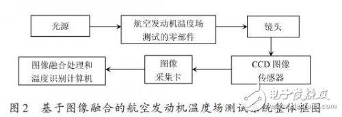
The work of the whole system is as follows: First, when the test target is close to the center of the CCD image sensor, the image acquisition card sends a start pulse to the CCD image sensor and the illumination device to activate the image sensor and the illumination device, and the CCD image sensor performs one frame of image. Scanning and output; then the image acquisition card converts the analog signal collected from the CCD image sensor into A/D conversion into digital signal; the image acquisition card sends the image signal to the image processing and temperature recognition computer for image fusion and temperature recognition. After processing, the computer finally displays the results of image processing, analysis, and target temperature recognition.
2.2 Light source
In the process of testing the system, the purpose of the light source selection is to obtain high-contrast target information and target image of the background information, to highlight the target features of interest and suppress background features that are not of interest, thereby greatly reducing the difficulty of the target image processing. Improve the robustness and measurement accuracy of the system. Therefore, the choice of the light source should follow the principles of large contrast, moderate brightness, uniform light source, and high robustness. At the same time, it also considers the factors such as service life, temperature influence, price cost and design difficulty. Commonly used light sources include LED lights, halogen lamps, fluorescent lamps and laser light sources. LED lamps are selected here because they have the advantages of stability, energy saving, adjustable brightness and long service life.
2.3 Image sensor
The image sensor is a key component of the test system to acquire images. After converting the test target optical signal into an electrical signal and converting it into a digital image signal by A/D, the digital image processing can be performed in the computer. At present, image sensors mainly include CCD and CMOS. CCD image sensor [1] is a new type of semiconductor solid-state image sensor, which is made up of CCD charge-coupled device. It has high integration, low power consumption, simple structure, impact resistance, long life, stable performance, high image quality, etc. Advantages are thus widely used. CMOS image sensors are fabricated using CMOS type photoelectric conversion devices, which are inexpensive but have poor image quality. Considering that the test system requires high image quality, a CCD image sensor is used here. This system installs multiple CCD image sensors to obtain images of test targets from different angles. The use of multi-sensor redundancy architecture also increases the robustness of the system.
2.4 lens
The lens is an important component of the test system. It images the test target on the light-sensitive surface of the CCD image sensor. The quality of the lens is directly related to the acquisition quality of the temperature field image of the engine component, and directly affects the performance of the overall system. In this test system, the selection of the lens in this test system follows the following three principles:
(1) Follow the high resolution;
(2) The imaging size should not be smaller than the target size of the CCD image sensor;
(3) Select the focal length of the lens based on the distance between the CCD image sensor and the target being tested. Multiple lenses are used here, each lens being aligned with a CCD image sensor.
2.5 image capture card
The image acquisition card converts the target analog image signal obtained by the CCD image sensor into a digital image signal, and the image acquisition card has an external signal interface connected to the CCD image sensor, and the image acquisition card is mounted on a bus socket of the computer. During operation, the image acquisition card first collects the analog image signal output by the CCD image sensor, and then converts the analog image into a digital image and stores it in the memory through A/D conversion, and the computer performs digital image fusion on the collected multi-source image. deal with. At present, image acquisition cards mainly include PCI and PXI. The image acquisition card based on PCI bus has the conditions of vibration, impact, temperature and humidity in industrial environment. Considering the high vibration and high temperature of the engine, the image acquisition card of the PCI bus is selected here.
2.6 image fusion processing computer
In order to reduce the manual interpretation error, image fusion and image processing must be performed before the temperature field recognition is performed by using the temperature paint image. The image fusion processing computer collects and stores the target image acquired from the CCD image sensor into the computer memory, and images the target image. Digital fusion and temperature identification processing are performed to obtain a test target temperature field distribution.
3 system software design
The software design flow of the engine temperature field test system based on image fusion is shown in Figure 3.
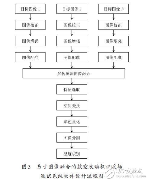
The whole software design mainly includes the following three parts: image fusion preprocessing and image fusion, fused image post-processing, and color temperature recognition of the target temperature paint image. Image fusion preprocessing refers to image correction of N target images obtained by N sensors at different angles, image enhancement, image registration preprocessing and image fusion. The purpose of image fusion is to expand the system's working range, improve system reliability and image spatial resolution, improve image accuracy, enhance feature display capabilities, provide change test capabilities, and replace or repair image data defects.
Commonly used image fusion algorithms include space-based image fusion and transform domain-based image fusion. In this paper, the wavelet fusion algorithm based on transform domain image fusion algorithm is used to fuse the target image. The algorithm has the advantages of removing feature correlation, providing multi-scale information, and strengthening the features and details of interest.
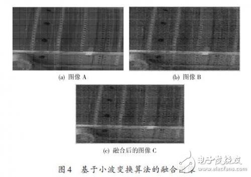
The result of image fusion based on wavelet transform algorithm is shown in Fig. 4. Image C is the image obtained by blending image A and image B. Here, the wavelet base coefficient is sym6, the number of decomposition layers is 3 layers, the low frequency is averaged, and the high frequency is taken. Coefficient weighting.
The three evaluation indexes of image fusion are calculated: information entropy, spatial frequency and average gradient. By comparing the numerical results of the calculation results, the three indicators of the merged image are obviously improved, which shows that the image quality and clarity after fusion are obvious. increased.
Image post-processing after image fusion: including feature selection, spatial transformation, color quantization, and image segmentation. Finally, the target image is temperature-recognized according to the color temperature characteristics of the temperature paint. The method for judging the temperature value of the temperature paint color image is as follows: To determine the temperature value of point A, it is necessary to find a point B on the curve closest to the point A, and the distance between point A and point B can be expressed by the Euclidean distance. If AB is the minimum distance, the temperature corresponding to point B is considered to be the temperature at point A.
4 Conclusion
In this test system, image fusion is the key to image processing, which directly determines the quality and clarity of image processing. The experiment proves that the system obviously improves the test efficiency and test accuracy of the engine temperature field, and has very good application and promotion value.
Metal Case IP65 Waterproof LED Driver
Ideal for indoor and outdoor installations, including street lighting and architectural illumination, these highly efficient LED Drivers are protected from dust and moisture, providing outputs up to 150W.
Top features include:
- Constant Voltage or Constant Current modes
- Protection: Short circuit / Over-voltage / Over-temperature
- High Efficiencies: Up to 91.5%
- IP67 designs for dry, damp or wet locations
- Fanless design: Cooling by free-air convection
- UL Recognized for US and Canada; FCC Class B
- Comprehensive 5 year warranty!

Waterproof LED Driver,0-10V Dimming,Street Light Driver,Waterproof Driver,Waterproof LED Driver,Wide Input AC,CUL Listed Driver
ShenZhen Fahold Electronic Limited , https://www.fahold.com