![<?echo $_SERVER['SERVER_NAME'];?>](/template/twentyseventeen/skin/images/header.jpg)
There are many different topologies for power supplies, but in fact we can understand one topology and understand other topologies. Because the basic elements that make up the various topologies are the same.
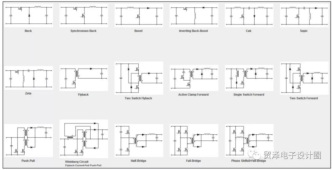
For isolated power supplies. The circuit topology that you are most exposed to should be flyback.
But when people start to do power, they don't design, and even the analysis doesn't understand. The only thing that can be done is imitation (the amount is plagiarized). After this state of state continued for a while, it began to slowly understand. But for beginners, if we can evolve from the basic topology BUCK, BOOST to a more complex topology, then it is very easy to understand the various topologies.
In fact, understanding the isolated power supply, compared to the non-isolated DCDC, you need to understand a basic element - the transformer. Then many basic principles can also evolve through the basic topology.
This article is an evolution of the process analysisTo analyze the flyback circuit, let's start with the source of the flyback. Flyback evolved from buck-boost in the most basic three circuits. So the analysis of buck-boost must help with the analysis of flyback, and buck-boost seems to be simpler than flyback, at least it has no transformer.
The next step is to begin the evolution of buck-boost, which will eventually evolve into a flyback.
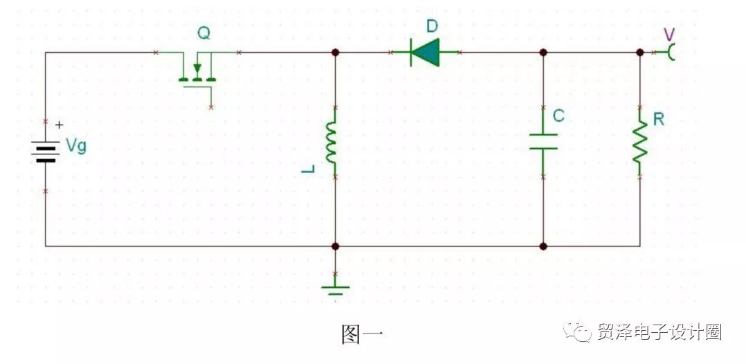
Buck-Boost circuit - a buck or boost chopper whose output uniform voltage U0 is greater or less than the input voltage Ui and has the opposite polarity.
Figure 1 shows the prototype circuit of buck-boost. Take the inductor L around a parallel coil, as shown in Figure 2:
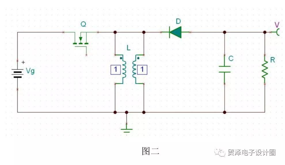
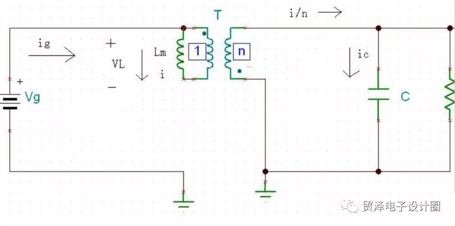
Disconnect the 2 parallel coils of L and change the turns ratio to: 1:n, as shown in Figure 3:
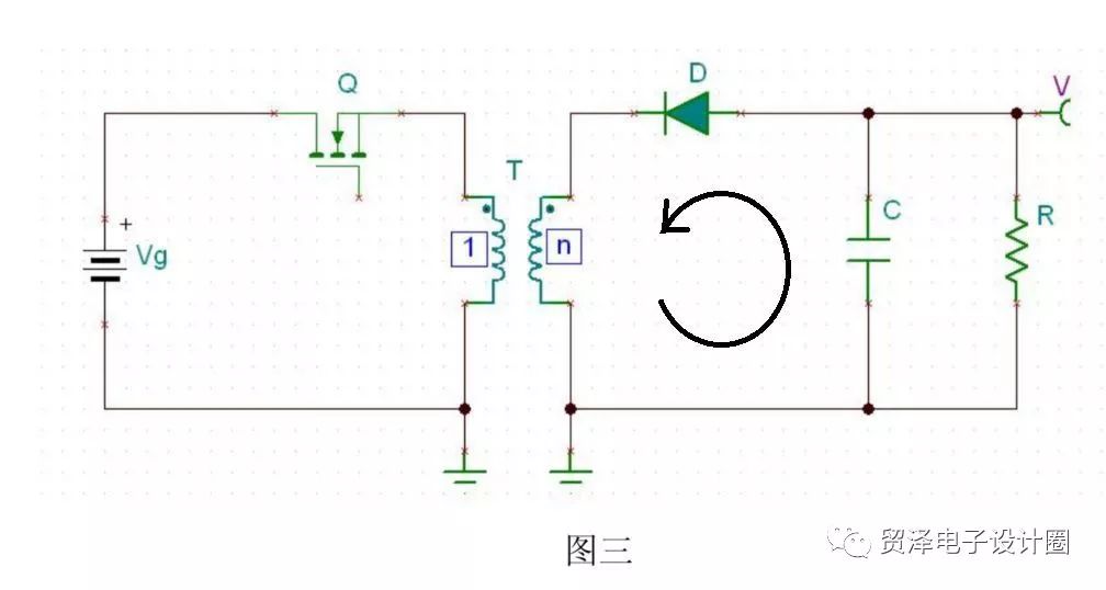
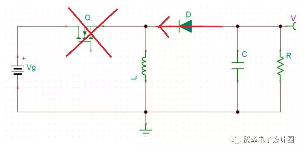
The diode in Figure 3 is moved along the loop, becoming the cathode facing outward, and changing the output voltage V and the grounded position. (The diode acts as a single-pass, and the circuit has no other branch currents. The effect can be equivalent at two locations in a loop.)
(Buck Boost is to achieve back pressure, but we do not need back pressure to isolate the power supply, so we need to change the polarity of the power supply.) Figure 4:

Move Q in Figure 4 along the loop to the bottom of the transformer, as shown in Figure 5: (The position of the switch can be anywhere, but we don't want the MOS open condition Vgs should not be too high.)
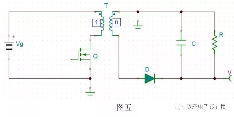
Change the winding direction of the transformer, then form Flyback
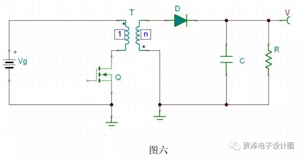
As explained above, we study the behavioral characteristics of buck-boost, which is very helpful for studying the behavior of flyback. Because the working process of the two circuits is very similar. Just in the buck boost topology, there is only one inductor for energy storage, and in the flyback circuit, it is a transformer. The electromagnetic energy on the primary side can transmit energy to the secondary side when the primary side circuit is suddenly disconnected.
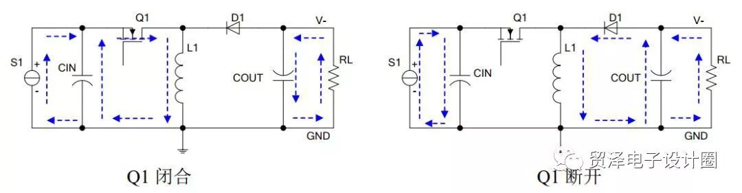
For the Buck-Boost topology:The first working state: mosfet Q is turned on and diode D is turned off. As shown in Figure 8:
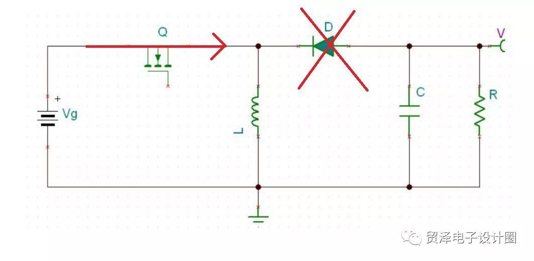
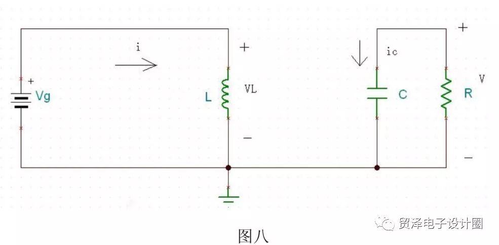
At this point, the input power source charges the inductor. The energy originally charged by the capacitor supplies power to the load and maintains its original voltage.
The second working state: Mosfet Q is turned off and diode D is turned on. As shown in Figure IX:
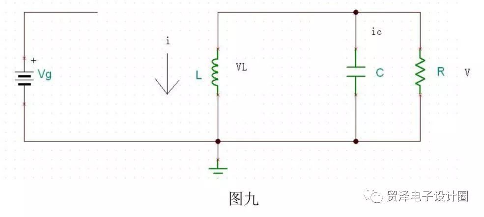
At this point, the inductor will maintain its original current.
Let's take a look at the working process of flyback:
Assume that this flyback circuit is still operating in a stable CCM state.
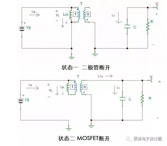
In state 1 mosfet Q is turned on, diode D is turned off, and the circuit is as shown.

Analogous to the state of the BuckBoost we just mentioned, the inductor is charged and the capacitor maintains the load current.
In the flyback state 2 Mosfet Q is turned off and diode D is turned on, at which point the secondary side of the transformer charges the load and capacitor.
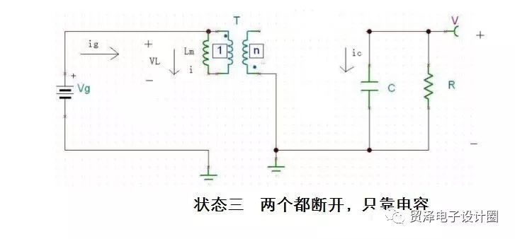
What we just discussed is the CCM situation. Flyback has an additional case of DCM.
The flyback operating in the DCM case has one more operating state than in the CCM. The working state 1 and the working state 2 are the same as the working states 1 and 2 of the CCM. In the working state 3, both the Mosfet Q and the diode D are turned off. State. The three working states experience time are d1Ts, d2Ts, d3Ts.
Ring And Fork Type Insulated Terminals
Ring And Fork Type Insulated Terminals,High quality insulated terminal,copper tube terminal
Taixing Longyi Terminals Co.,Ltd. , https://www.longyiterminals.com