![<?echo $_SERVER['SERVER_NAME'];?>](/template/twentyseventeen/skin/images/header.jpg)
Due to the low cross-section, light weight, and easy processing of microstrip antennas, such antennas are becoming more and more widely used in military and civilian applications. Especially in recent years, the rapid development of SAR (Synthetic Aperture Radar) technology has put forward higher and higher requirements for microstrip antennas. It is hoped that broadband, large scanning angle, high efficiency and low crossover can be obtained simultaneously on one antenna. The performance, and has the advantages of simple feeding, easy integration with the feeding system and so on.
The microstrip patch antenna has a variety of feeding modes. Among them, the microstrip line coplanar feeding is the simplest in structure, and the integrated design of the feeding network is easy to implement and the application is wider. The microstrip-fed rectangular microstrip patch antenna has been one of the most widely used microstrip unit forms since its publication. However, such a rectangular microstrip antenna is in a single layer form with a narrow bandwidth (typically "3%") and the feed position is limited to the radiant side. Subsequently, scientists and technicians at home and abroad made a lot of research on various types of rectangular microstrip antennas. In order to broaden the working bandwidth, a two-layer microstrip patch antenna with radiated edge feeding is introduced. The lower layer patch is the feeding element, the upper layer conductor patch is the parasitic element, and the middle layer is a low dielectric constant dielectric layer. The structure uses dual resonance to widen the operating frequency band, and the maximum working bandwidth of the antenna can reach about 10%.
It is the first to introduce a single-layer rectangular patch antenna with non-radiative edge coplanar feeding. When the unit is used in the design of microstrip coplanar feeder array antenna, the length of the feeder can be shortened and the design of the feed network can be simplified. Therefore, it can be used as a high-efficiency microstrip array antenna design, but it has the same narrow bandwidth as a conventional single-layer rectangular microstrip antenna. Recently, the patent provides a cross-polarization suppression technique for a radiating edge-fed double-layer rectangular microstrip antenna by simultaneously opening four or more slits on the upper and lower radiation patches, and the orientation of the slits is The polarization direction of the antenna is the same, and the purpose of suppressing the cross polarization of the antenna unit is achieved by suppressing the mode current of the cross polarization.
Combining the above various technologies, this paper introduces a novel double-layer microstrip patch antenna with non-radiative edge feeding, and studies the performance characteristics of the antenna and its application in the array.
2 unit structure and simulation test resultsThe structure of the antenna unit is shown in Figure 1. The same structure as the common double-layer microstrip patch antenna is used for broadband operation. The whole antenna is mainly composed of a feeding microstrip layer, a foam layer, a parasitic microstrip layer and a grounding structure. The board is composed of four parts. The feeding microstrip is etched with a feeding patch and a feeding microstrip line, and the parasitic microstrip is etched with a parasitic patch to protect the parasitic patch. The parasitic element patch in the figure adopts an inverted structure.
Different from the traditional double-layer microstrip patch antenna design, the bottom rectangular patch uses the non-radiative edge feeding of the microstrip line. The advantage of this feeding method is that the design of the feeding network can be simplified, but with The problem is that the antenna will excite the TM10 cross-polarization mode in addition to the main mode TM01 mode, which will deteriorate the cross-polarization performance of the antenna. For single-layer rectangular microstrip patch antennas, the literature [3] proposes to suppress the TM10 mode by selecting the aspect ratio (1.5:1) of the appropriate rectangular patch. However, the simulation results of HFSS show that the effect of the simple adjustment of the aspect ratio of the patch on the double-layer microstrip patch is limited, although the maximum cross-polarization in the band under the optimal aspect ratio (1.5:1) can reach -10dB. Left and right; but at this time the antenna has a lower radiation impedance, and broadband impedance matching is difficult. In order to solve the above problem, in addition to properly controlling the aspect ratio of the rectangular patch, the parasitic patch is also opened in the direction perpendicular to the radiation side, and some evenly distributed elongated slits are opened, and the surface current of the cross polarization mode is cut. The purpose of suppressing the cross polarization mode of the antenna is achieved. The simulation results show that the in-band cross-polarization of the antenna tends to be stable when the number of uniformly distributed gaps reaches more than three and Ls ≥ 0.8W2.
In order to verify the above research results, using HFSS to optimize the design results, an X-band non-radiative edge-fed double-layer microstrip antenna unit was designed according to the following parameters: er1=2.94, h1=0.508mm; er2=1.07, h2=3.0 Mm; er3 = 4.39, h3 = 0.254 mm;
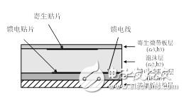
a) Sectional view
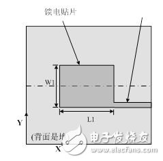
b) Feed micro strip circuit diagram
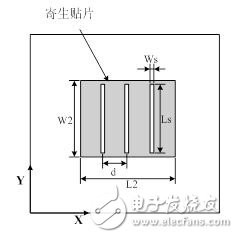
c) Parasitic microstrip board circuit diagram
W1 = 8.7 mm, L1 = 9.7 mm; W2 = 9.2 mm, L2 = 11.3 mm; Ws = 0.5 mm, Ls = 7.7 mm. The test results of the antenna show that Vswr ≤1.2 in the bandwidth of 15.5%, and the cross polarization of the two main faces in the band is better than -16dB. Figure 2 shows the simulation and test results of the port standing wave curve. Match. It can be seen that compared with the common double-layer microstrip patch antenna, the impedance bandwidth of the new unit is about 3-5% wide, and the cross-polarization index is equivalent.
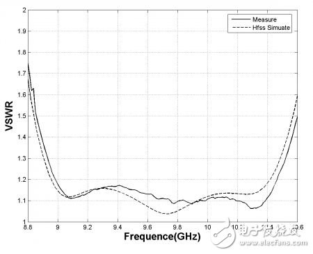
Figure 2 Simulation and test results of unit standing wave characteristics
3 antenna unit application in array designThe novel two-layer patch antenna unit proposed above can be flexibly applied to the design of a broadband coplanar concentrated feeding microstrip array antenna, and a novel antenna similar to the conventional radiation-feeding double-layer microstrip patch unit. The unit can simplify the feeding circuit of the antenna array, improve the feeding efficiency, and realize the broadband and high-efficiency coplanar feeding antenna array; especially when applied to the microstrip line array design, it is beneficial to save the feeding space and facilitate the design of the large scanning angle. Antenna array. Figure 3 shows a comparison of the various array modes of the two microstrip patch units.

a. radiated edge feed b. non-radiative side feed
Figure 3 Comparison of the array mode of two microstrip units
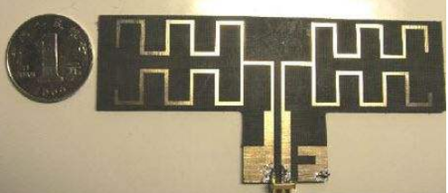
Using the X-band 8 & TImes; 8 microstrip antenna experimental small array designed by the new antenna unit, the schematic diagram of the feeding circuit of the small array and the physical photo are shown in Fig. 4. The small array is composed of 8 1&TImes; 8 microstrip line arrays, and the line Each unit in the array is equally propagating in phase. In actual application, each line source is fed by T/R component, which can realize one-dimensional ±25° scanning, to suppress the cross polarization of the antenna, between adjacent line arrays. Mirror image arrangement, inverting each other when feeding. In the microwave darkroom, the technical indexes of this passive small array are tested. The results show that the standing wave ratio of each line array is better than 1.6 in the 17.6% frequency band, and the cross polarization of the whole small array is better than -30dB. The maximum sidelobe level is better than -11dB, and the in-band antenna efficiency is better than 70%. Figure 5 and Figure 6 show the test results of the port standing wave measured curve and the typical pattern of the line array direction of each line array. From these results, it can be seen that the antenna exhibits a good performance index in a wide frequency band.
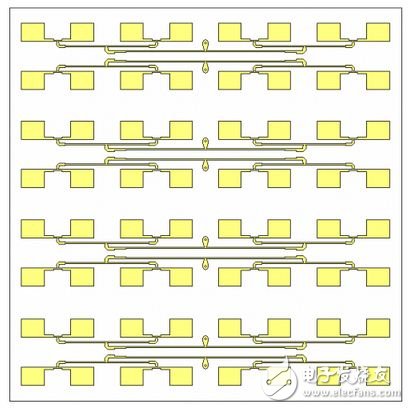
(a) Feed circuit
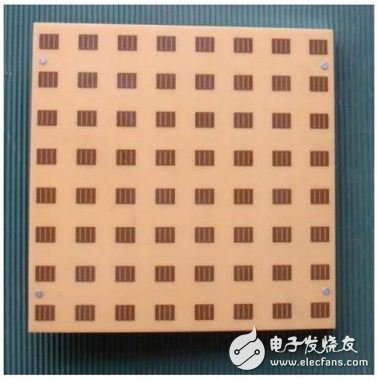
(b) Physical photos
Figure 4 X-band 8 & TImes; 8 unit antenna small array diagram
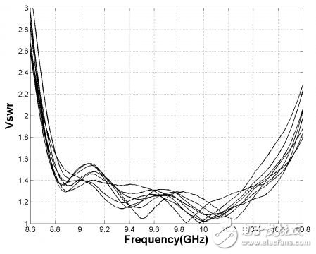
Figure 5 8 & TImes; 8 small array of port line standing wave test curve
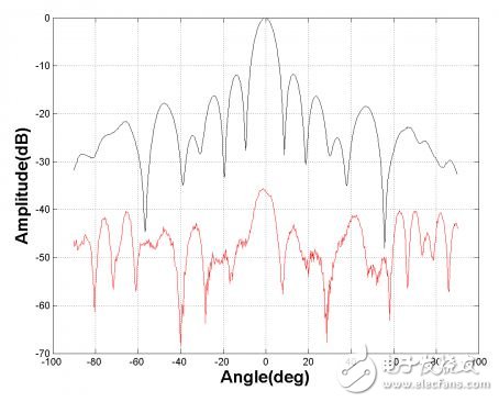
Figure 6 Typical pattern of 8 × 8 small array line direction
4 ConclusionThe simulation and experimental results show that the non-radiative edge-fed double-layer microstrip patch antenna has good broadband working ability. When it is applied to the design of the coplanar concentrated feed microstrip array antenna, the antenna array can be simplified. The electric circuit improves the feeding efficiency and facilitates the realization of a broadband and high-efficiency coplanar feeding antenna array; especially when applied to the microstrip line array design, it is advantageous to save the feeding space and facilitate the design of the antenna array with a large scanning angle. It is foreseeable that such antenna units have broad application prospects in radar and communication systems.
SHENZHEN CHONDEKUAI TECHNOLOGY CO.LTD , https://www.szfourinone.com