![<?echo $_SERVER['SERVER_NAME'];?>](/template/twentyseventeen/skin/images/header.jpg)
1 Introduction
This article refers to the address: http://
With the development of electromechanical technology, electronic technology has also penetrated into the brake system of automobiles, and a new technology called "electronic brake system" has emerged. Unlike conventional automotive brake systems, the electronic brake system replaces most of the hydraulic and mechanical components with electronic components, reducing the lag time of the mechanical transmission of the brake system. According to the driver's braking operation, the pedal stroke sensor detects the driver's braking intention, and then precisely controls the braking force of each wheel, shortening the braking distance, thereby increasing traffic safety [1].
2, EMB
BBW system is currently divided into two types, one for the electric brake system EHB (Electro-hydraulic Brake), another for the electro-mechanical brake EMB (Electro-Mechanical Brake) [2]. The main content of this article is the latter.
Compared with the traditional brake control system, the electromechanical brake system has the following advantages [3]:
1 The system is simple in structure, eliminating a lot of piping systems and components;
2 The brake response time is short, which improves the braking performance;
3 System manufacturing, assembly and testing are simple and fast, adopt modular structure and easy maintenance;
4 With wire connection, the system has good durability;
5 Easy to improve, a variety of electrical control functions can be added with a slight change.
The electromechanical brake system consists of the following parts:
1 Power supply: Use vehicle power supply.
2 Electric brake: Use a torque motor that can be continuously blocked.
3 Electric brake control unit (ECU): It consists of two parts, the master control node and the slave control node. The main control node is responsible for receiving the signal from the brake pedal sensor, and after a certain algorithm calculation, sends the data to the slave node to control the brake braking; receives the wheel sensor signal, and recognizes whether the wheel is locked or slipped. The slave control node is responsible for receiving the data message sent by the autonomous node, and driving the torque motor rotation direction and the rotation torque according to the content of the data message.
4 Wheel speed sensor: The Hall sensor is used to generate pulses during wheel rotation and is collected by the ECU.
3. Hardware design of EMB system
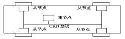
Figure 1 System schematic
3.1 master node hardware structure
Considering that the main node needs to process more data, the real-time response requirements are relatively high. Therefore, a 16-bit microcontroller with strong computing power is used. Here we use Infineon's XC164CM8F40F. It uses a high-performance 16-bit C166S V2 CPU pipeline with 5 to provide better performance and an interrupt process and the DSP peripheral set of high performance and reliability of the flash memory chip, 40MHz CPU clock time of 25ns single instruction, and 16 priority Interrupt the system with up to 75 interrupt sources.
In terms of peripherals, it has 14 ADCs, multi-function universal timer unit, on-chip TwinCAN interface, 47 GPIOs, and rich peripheral resources such as on-chip debugging through JTAG interface.
The XC164CM contains two sets of five general-purpose timer/counters, one of which is used as a timer to calculate the speed of the vehicle and the rate of change of the pedal stroke; the other four are used as counters to collect the pulse signal from the Hall sensor mounted on the wheel.
The analog voltage value of the pedal stroke sensor is acquired using an ADC. In terms of CAN bus interface, the on-chip TwinCAN module supports the CAN specification V2.0A/B, which greatly simplifies the CAN interface application design. Using one CAN controller in the on-chip TwinCAN module, the external TLE6250 is used as the physical interface of the CAN bus to realize CAN bus communication.
3.2 system slave node hardware structure
The system needs four identical slave nodes, and the functions to be implemented by the slave nodes are relatively simple. Only the data message needs to be received from the CAN bus, and the rotation direction and torque of the motor are controlled according to the content of the message. The T89C51CC01 microcontroller with a lower price for the internal CAN controller. The motor drive chip adopts the full-bridge motor drive chip VNH3SP30 of ST company's single package. The chip is packaged in a compact package that saves board space, weight and cost. The product's special win includes 30A output current, 40V maximum working voltage, and supports pulse width modulation operation up to 10KHz.
4. Software design of EMB system
4.1 master node software design
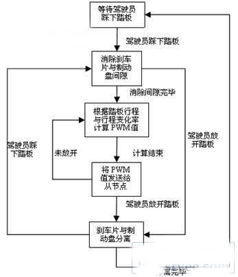
Figure 2 main node software flow
The program first waits for the driver to step on the pedal. Since there is a certain distance between the brake pad and the brake disc in the non-braking state, when the driver just steps on the springboard, the torque motor needs to quickly eliminate the gap between the brake pad and the brake disc. After eliminating the clearance, the program should be able to control the torque output by the torque motor according to the stroke of the pedal. Since the torque motor is always in a stalled state after the gap between the brake pad and the brake disc is eliminated, the torque output can be precisely controlled by the torque motor output PWM signal pulse width modulation.
The monitoring of the driver's braking intention is made possible by the use of an electronic braking system. For example, in an emergency, the driver quickly depresses the brake pedal. In a conventional brake system, the maximum braking force is provided when the pedal is stepped to the bottom. In the electronic brake system, if an emergency occurs, the intention to drive the emergency brake may be sensed in advance, and the maximum braking force may be provided when the driver does not step on the brake pedal to the bottom, which may greatly increase the system. Dynamic security. Based on the above considerations, the braking force cannot simply correspond to the pedal stroke, and the intelligent fuzzy control method is required to nonlinearly control the braking force.
When the driver completely releases the brake pedal, although no braking force is provided at this time, the brake pad and the brake disc are still in contact. In order to minimize the drag torque, the brake pad needs to be removed from the brake disc for a short period of time. Distance, which is the process corresponding to the elimination gap when the driver steps on the pedal.
4.2 slave node software design
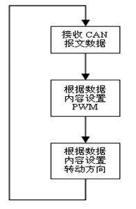
Figure 3 slave node software flow
The work to be done by the slave node is relatively simple. The slave node only needs to receive the data sent by the CAN bus, and controls the torque motor by using the IO interface to control the rotation direction of the motor and the PWM signal to the driver chip according to the data content. Torque.
4.3 Implementation of key technologies
4.3.1 Pedal stroke collection
The pedal stroke sensor uses an angular displacement sensor to acquire an analog signal through the analog-to-digital conversion interface module of the master node. Since the brake system is a relatively important part of the car, the safety requirements of the brake device are high, so the design of the pedal stroke sensor adopts a redundant design method. One implementation method here is to design two sets of sensors, and the analog voltage value generated by the two sets of sensors corresponds to a double relationship corresponding to a certain stroke, so that the collected and calculated pedal stroke value has high safety.
4.3.2 Calculation of pedal stroke change rate
In the timer mode, the current pedal stroke value is compared with the previous pedal stroke value every fixed time, and the rate of change of the pedal stroke is obtained. However, in order to reduce the jitter and smooth the rate of change curve, the formula (1) can be used.
![]() (1)
(1)
Where dL is the rate of change to be calculated, dL0 is the rate of change calculated this time, and dL1 and dL2 are the values ​​of the rate of change of the previous two times.
4.3.3 Calculation of braking force
Because in the electronic brake system, the algorithm for calculating the braking force requires greater flexibility, such as the ability to change the algorithm parameters according to different models. Therefore, the PWM output value can be calculated by using the fuzzy control method which is more flexible and less computationally capable, and the pedal stroke value and the pedal stroke change rate value can be used to control the braking force.
The specific algorithm is as follows:
1 fuzzification.
Enter the variable pedal stroke L, the domain is: {Z, PS, PM, PL}, using the triangle membership function, as shown in Figure 4.
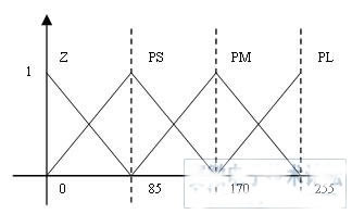
Figure 4 pedal travel membership function
Enter the variable pedal stroke change rate dL, the domain is: {NL, NS, Z, PS, PL}, using the triangle membership function, as shown in Figure 5.
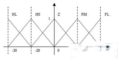
Figure 5 pedal travel rate change membership function
The output variable is defined as the PWM value of the solution, and the domain is: {Z, PS, PM, PL}.
The fuzzification variable is a membership value that converts the value of the input variable to the value of each element in the universe according to the membership function.
2 fuzzy reasoning:
When the two input variables are blurred, the next step is to make fuzzy reasoning based on the inference rule table.
Table 1 Fuzzy inference rule table
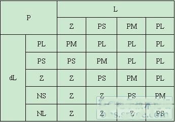
The leftmost column in the table is the fuzzification domain corresponding to the stroke change rate dL, and the most upward is the fuzzification domain corresponding to the stroke L. The rest of the table is the fuzzification domain corresponding to the PWM value to be solved.
In the calculation, the membership value is calculated for each element in the middle part of the table in turn by multiplying the membership degrees of the corresponding L and dL. Finally, the same element membership values ​​are added to obtain a set of fuzzy vectors of output variables: (Z, PS, PM, PL)
3 defuzzification:
According to the membership function of the PWM value in the figure below, the center of gravity method is used to calculate the final PWM output value.
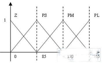
Figure 6 Output PWM value membership function
The calculation method of the center of gravity method is shown in formula (2).
![]() (2)
(2)
The exact value thus obtained is the final PWM output value.
5 Conclusion
In this paper, the current popular car CAN bus network is used to realize the basic functions of EMB in a simple way, with high real-time and time responsiveness. The network control method is adopted to set the specific implementation of the drive motor to the terminal, and the microcontroller with weak processing capability and low price is adopted; and the microcontroller with relatively high processing power and relatively high price is adopted at the main control end. Improve the rationality of the overall design. The fuzzy control method is adopted in the security control, and the biggest feature of the fuzzy control method is that it has strong flexibility, and the flexible modification of the control method can be performed according to the needs, so that the braking mode of the brake is more reasonable.
This system has passed the bench test to verify its feasibility in the “Research and Development of Automotive Line Control System Electronic Control Unit†project of Zhejiang Asia-Pacific Mechanical & Electrical Co., Ltd.
references
[1] Song Jeonghoon.Performance evaluation of a hybrid e-lectric brake system with a sliding mode controller [J] .Mechatronics, 2005, (15): 339-358.
[2] Lin Muyi, Zhang Wenming, Ning Xiaobin.Implementation of Line Control System on Wheeled Industrial Vehicles[J].Machine Tool & Hydraulics,2004,8:145-146.
[3] Liu Wei, Liu Fangming, Lin Muyi. Industrial vehicle line control dynamic system [J]. Mechanical Management Development, 2004, 10: 26-27.
Laser cutting provides greater precision in stator and rotor machining, using a highly focused beam that acts as a heat-affected zone during cutting without causing extensive thermal damage to adjacent surfaces. The finishing is cleaner, smoothing the edges of complex shapes and designs. Laser cutting machine with computer numerical control function, laser cutting process can be automatically controlled by the pre-designed machine program. CNC controlled laser cutting machines reduce the risk of operator error and produce more precise, precise parts with tighter tolerances.
The use of laser cutting method can reduce the total lead time, the total cost of production. For laser cutting, it can be processed by drawing, without making molds, and without mold replacement and setting between materials or material thickness. Compared with traditional cutting methods, laser cutting setup times can be greatly reduced and it involves more machine programming than loading materials.
Lower material cost
Our current production technology supports laser cutting for stator and rotor production.
Stator And Rotor Lamination With Laser Cutting
Henan Yongrong Power Co., Ltd , https://www.hnyongrongglobal.com