![<?echo $_SERVER['SERVER_NAME'];?>](/template/twentyseventeen/skin/images/header.jpg)
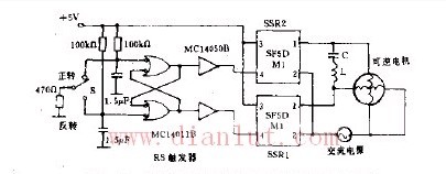
As shown in the figure, the signal provided by the SW is latched by the RS flip-flop to trigger SSR1 or SSR2 to be turned on, so that current can flow in one of the two windings of the single-phase induction motor, thereby the motor rotates forward or reverse. . The resistors and capacitors on the input side of the RS flip-flop are designed to provide a rest time of approximately 100 ms during forward and reverse conversion. That is, the delay time of the capacitor charging is used, and both SSR1 and SSR2 are turned off during the 100 ms period after the conversion to protect the SSR.
Uni Directional Mic,Uni Directional Microphone,Uni Directional Dynamic Microphone,Uni Directional Condenser Microphone
NINGBO SANCO ELECTRONICS CO., LTD. , https://www.sancobuzzer.com