![<?echo $_SERVER['SERVER_NAME'];?>](/template/twentyseventeen/skin/images/header.jpg)
The lighting system is part of a sub-system in the smart home and can also be used separately. The lighting system can control various lighting effects in different living areas and different occasions to easily solve the problem of home energy saving and improve the quality of life. This problem is often encountered in life. When watching TV or reading in the living room, it does not need too much illumination. The living room headlights have to be turned off to turn on the light to be used to meet other lighting needs for watching TV or reading. In order to meet the lighting requirements of different occasions, it is necessary to install a variety of lamps, which brings great inconvenience to the control of the lamps.
The solution for lighting system control is divided into wired and wireless. Wired methods include X-10 and CEBUS for power line carrier, HomePNA for telephone line mode, IEEE802.3 for Ethernet mode, and LONWORKS and IEEE1394 for dedicated bus mode. The advantage of using power line as the transmission medium of network information is that there is no need to separately lay cables and reduce the construction difficulty; the disadvantage is that the transmission rate is only 300Kbps, which is difficult to meet the transmission of video and audio signals, the confidentiality is poor, and the access equipment is expensive. Wireless methods include infrared-based IrDA, wireless LAN-based IEEE802.11 series, home RF technology HomeRF, Bluetooth IEEE802.15.1, ZigBee's IEEE802.15.4, and so on. The wireless solution solves the wiring problem and also satisfies the transmission of video and audio signals. This article introduces a smart home lighting system based on 2.4G RF technology.
This scheme adopts STC12C5A08AD as the MCU controller. STC12C5A08AD is a new generation of single-chip microcomputer. It adopts the 6th generation secret technology. After the program is programmed, it cannot be decrypted, which enhances the security function. The speed is 8~12 times faster than the ordinary 8051 MCU, and there are 4 16-bit timers built in, which consumes less power. The control signal of the MCU controls the thyristor to control the brightness of the luminaire through the optocoupler. A current detection loop is added to the high-voltage control interface to detect the magnitude of the strong current, which is used as detection feedback. The communication method adopts 2.4G wireless communication module, which requires no wiring, reduces cost, flexible control mode, wide range of remote control and fast communication speed. This program can control 12 channels of lamps for home lighting control.
2.4G Bluetooth module circuit design
Commonly used in general-purpose chips for 2.4GHz communication are the nRF2401 wireless chip module and the RFW102 wireless chip module. According to design requirements and cost considerations, nRF2401 is used in this design for wireless data transmission. The nRF2401 is a single-chip wireless transceiver that operates in the 2.4GHz ISM band and is fully integrated with power synthesizers, power amplifiers, crystal oscillators and tuning circuitry. QFN24 5 & TImes; 5 mm package, application circuit uses fewer external components; FSK modulation, 125 channels, can meet multi-frequency and frequency hopping needs; transmission rate up to 1Mbps, high data throughput; low power consumption, power supply voltage 1.9V~3.6V meets the needs of low-power design; the chip has a special voltage regulator circuit inside, and all kinds of power supplies, including DC/DC switching power supply, have good communication effects.
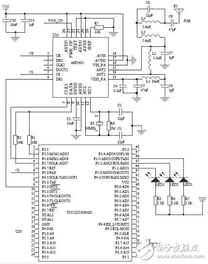
Figure 2 2.4G communication circuit
Intelligent lighting control circuit design
Commonly used dimming methods are: pulse width modulation (PWM) dimming method, changing half-bridge inverter supply voltage dimming method, pulse frequency modulation dimming method, pulse phase modulation dimming method and thyristor phase control dimming method. . The controllable phase-controlled dimming method has the advantages of small size, reasonable price and wide dimming power range. The system finally adopts thyristor phase-controlled dimming to adjust the brightness of the lamp.
Applying the principle of thyristor phase control, by controlling the conduction angle of the thyristor, the sinusoidal voltage input to the grid is cut off to reduce the average value of the output voltage, and the power supply voltage of the lamp is controlled to realize dimming. The thyristor phase-controlled dimming has a fast voltage adjustment speed for the illumination system, high dimming precision, and the dimming parameters can be adjusted in real time in different time periods. Since the dimming circuit is mainly composed of electronic components, the volume is relatively small, the equipment is light in weight, and the cost is low. The thyristor phase-controlled dimming circuit is shown in Figure 3. The control signal of the single chip microcomputer is inverted by 74HC04 and sent to the optocoupler MOC3023. After photoelectric isolation, it is input to the control electrode of the thyristor T16C6F to control the conduction angle of the thyristor to realize dimming.
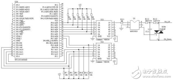
Figure 3 thyristor phase-controlled dimming circuit
Electronic enthusiast network technology editors comment analysis:
The lighting system based on single-chip control has the advantages of low cost, short development time, convenient installation and maintenance, and easy to meet different needs of customers, and has a broad market prospect. At present, China's consumption level is not high, and the huge high-end demand for the system is not large, and the low cost of the lighting system is more and more widely used in the home market. The lighting system based on single chip control introduced in this paper has certain marketing value.
If you have any questions, please feel free to discuss them in the comments section.
- Electronic enthusiast network finishing, please indicate the source!
220Uh Inductor,High Current Inductor,Power Inductor,Toroidal Core Inductor
IHUA INDUSTRIES CO.,LTD. , https://www.ihua-magnetics.com