![<?echo $_SERVER['SERVER_NAME'];?>](/template/twentyseventeen/skin/images/header.jpg)
Freescale's MC9S12XHY series is a 16-bit microcontroller with high-performance 32-bit features. The CPU12XV1 CPU core has up to 40MHz bus frequency, supports CAN and LIN/J2602 communication, and provides up to four stepper motor controls and 40x4 LCD. Drive, up to 245KB of on-chip flash with ECC features and 8KB of data flash, 12KB of on-chip SRAM, etc. Targets are used in low-end dashboards, automotive HVAC stepper motors and automotive audio systems. This article describes the main features of the MC9S12XHY256, block diagrams, and DEMO9S12XHY256 demo board main features and circuit diagram.
This article refers to the address: http://
The MC9S12XHY family is an optimized, automotive, 16-bit microcontroller product line focused on low-cost and high-performance. This family is intended to bridge from low-end 16-bit microcontrollers, such as MC9S12HY family, to high performance 32- Bit solutions. The MC9S12XHY family is targeted at the lower end of automotive instrument cluster applications, it includes support for CAN and LIN/J2602 communication and delivers typical cluster requirements such as stepper motor control with stepper stall detection (SSD) and LCD Driver.
The MC9S12XHY family delivers all the advantages and efficiencies of a 16-bit MCU while retaining the low cost, power consumption, EMC, and code-size efficiency benefits currently enjoyed by users of Freescale's existing 8-bit and 16-bit MCU families. Like The MC9S12XHY family, the MC9S12XHY family will run 16-bit wide accesses without wait states for all peripherals and memories. The MC9S12XHY family will be available in 100-pin LQFP and 112-pin LQFP package options and aims to maximize pin compatibility with the MC9S12HY Family in the 100 LQFP. In addition to the I/O ports available in each module, further I/O ports are available with interrupt capability accommodation wake-up from stop or wait modes.
Main features of MC9S12XHY256:
CPU12XV1 CPU core, with up to 40Mhz bus frequency
Up to 256 Kbyte on-chip flash with ECC and 8Kbyte data flash with ECC.
Up to 12Kbyte on-chip SRAM
Up to 40x4 LCD driver
Stepper Motor Controller with up to drivers for up to 4 motors, plus four Stepper Stall Detector modules (one for each motor)
Phase locked loop (IPLL) frequency multiplier with internal filter, supporting 4–16 MHz amplitude controlled Pierce oscillator
Pulse width modulation (PWM) module and Two timer modules (TIM0 and TIM1)
Up to 12-channel, 10-bit resolution successive approximation analog-to-digital converter (ATD)
Serial peripheral interface (SPI) module and Inter-IC bus interface (IIC) module
Two serial communication interface (SCI) module supporting LIN communications
Two multi-scalable controller area network (MSCAN) module (supporting CAN protocol 2.0A/B)
On-chip voltage regulator (VREG) for regulation of input supply and all internal voltages
Autonomous periodic interrupt (API) and up to 25 key wakup inputs
MC9S12XHY256 target application:
Low end instrument cluster
Automotive HVAC stepper motor based actuator
Automotive Audio system
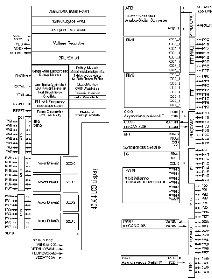
Figure 1. Block diagram of the MC9S12XHY series
DEMO9S12XHY256 Demo Board
The DEMO9S12XHY256 is a demonstration board for the MC9S12XHY256 microcontroller. Application development is quick and easy with the integrated USB-BDM, sample software tools, and examples. An optional BDM_PORT port is also provided to allow use of a BDM_PORT cable. A 40-pin Adapter provides access to most IO signals on the target MCU.
Main features of the DEMO9S12XHY256 demo board:
On-Board 4x40 Custom LCD Glass
2 ea. High-Speed ​​CAN Physical Layer Transceivers
Enhanced LIN Physical Layer Transceiver
RS-232 Serial Data Physical Layer Transceiver
Integrated USB-BDM. BDM_PORT header for external BDM cable support
MCU_PORT pin header for access to MCU IO signals
On-board +5V regulator
Optional Power from USB-BDM or MCU_PORT connector
Power Input Selection Jumpers, select from USB-BDM, on-board regulator, Connector J1. Optional Power output through Connector J1
User Components Provided, including 5 Push Switches, 6 LED Indicators, 5K ohm POT w /LP Filter
User Option Jumpers to disconnect Peripherals
Connectors, including 40-pin MCU I/O Pin Header, Barrel Connector, BDM_PORT Connector for External BDM Cable, USB/DB9/CAN cable/LIN cable Connector
The DEMO9S12XHY256 demo board includes:
DEMO9S12XHY256 Demo Board
DEMO9S12XHY256 user guide
"Quick Start Guide" sheet
a USB cable
a RS232 SERIAL cable
CodeWarriorTM Development Studio Special Edition CD-ROM
AXIOM 68HC12 development System support CD-ROM
Warranty card
Technical Information Center sheet
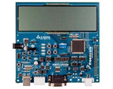
Figure 2. Outline drawing of the DEMO9S12XHY256 demo board
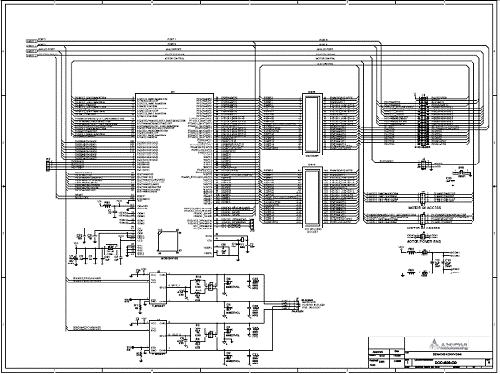
Figure 3. Circuit diagram of the DEMO9S12XHY256 demo board (1)
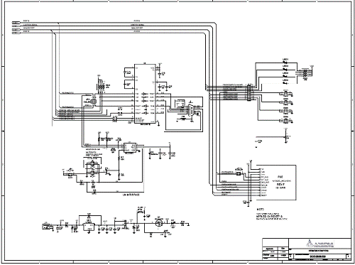
Figure 4. Circuit diagram of the DEMO9S12XHY256 demo board (2)
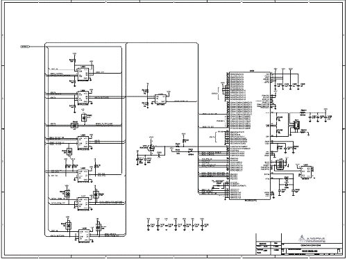
Figure 5. Circuit diagram of the DEMO9S12XHY256 demo board (3)
This range of extremely rugged 'skeleton' cable drums is particularly suited to life on the road but also at home in a TV or film studio. They are constructed from heavy-duty, welded, steel tubing, on to which an overall passivated zinc plate is applied. A traditional two-flange type is suitable for triax camera cable, multicore audio cable and heavy-duty power cables. An innovative three-flange design is suitable for coiling and protecting the inner 'tail' of SMPTE 311M hybrid fibre camera cable. An optional combined trolley and reeling stand is available for transporting the drums.
Skeleton Reel,Steel Tube Reel,Galvanized Reel,Studio Reel,Cable Trolley
NINGBO BEILUN TIAOYUE MACHINE CO., LTD. , https://www.spool-manufacturer.com