![<?echo $_SERVER['SERVER_NAME'];?>](/template/twentyseventeen/skin/images/header.jpg)
Summary:
As we all know, power circuit design is the most basic work in the overall circuit design. Therefore, in the following article, we will discuss the case of physical power circuit design.
* Reference power supply circuit with variable output voltage (characteristics: use dedicated IC reference power supply circuit)
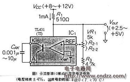
1 is a reference power supply circuit composed of a shunt regulator IC. This circuit can use the setting of the external resistors Vr1 and R3 to change the output voltage within the range of 2.5V to 5V. The output voltage Vout can be obtained by the following equation. Get:
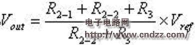 ----------------------(1)
Vref: Internal reference voltage.
In the figure, TL431 is the TI number, NEC number is μPC1093, New Japan Radio number is NJM2380, Hitachi number is HA17431, and Toshiba number is TA76431.
※High-precision reference power supply circuit with variable output voltage (characteristics: high precision, variable voltage)
Similar to REF-02C, which is a high-precision, non-variable reference power supply IC, it is necessary to add the OP amplification IC of Figure 2, and use the gain of the IC to make the output voltage variable, and its voltage variation range is 5- 10V.

※Power supply circuit with positive and negative voltages while standing with a single power supply (characteristics: positive and negative voltages stand at the same time)
Although the power supply unit of the battery device usually consists of a single power supply circuit, in some cases, the power supply circuit is required to have a negative power supply voltage.
The power supply circuit of FIG. 3 can output a stabilized positive and negative power supply sent from a single power supply. Generally, this type of power supply circuit uses a positive voltage as a reference to generate a negative voltage, so the negative voltage is relatively slow to stand, but the power supply of FIG. The positive and negative voltages of the circuit can stand at the same time. The TPS60403 IC in Figure 4 can reverse the polarity of the input voltage.
※Serial Regulator with a maximum output voltage of 40V (characteristic: high voltage that cannot be supplied by the three-terminal Regulator IC)
Although the output voltage of the three-terminal Regulator IC is about 24V, if the voltage is exceeded, the circuit design must be integrated with the IC and other components such as disk lead.
The Serial Regulator of Figure 5 can output a maximum voltage of 40V. In the figure, the output voltage of the D2 Zener diode is set to about half, and then the output voltage is divided by R7 VR1 R8 so that the voltage can be consistent with the voltage of VZ2. Decide on the number. It must be noted that if R7 R8 is too large, it will cause problems such as rising voltage noise and fluctuation of output voltage; if R7 R8 is too small, there will be heat and power loss, so R7 R8 2-5K is generally suitable.
※Serial Regulator with output voltage of 40-80 (feature: output high voltage with disk lead component)
Figure 6 shows a Serial Regulator that can output a voltage of 40-80. Since the output voltage of this circuit is very high, the OP amplification IC cannot be used. The VCEO in the figure is an error amplifier using a 120V 2SC2240-GR. In addition, this circuit adds TR5 and Cascode amplifiers to improve the frequency characteristics of the error amplifier.
2SK373-Y is a VDS=100V FET, which can form a high withstand voltage constant current power supply. In addition to the FET, a maximum current of 100V can be used, and the rated power is 300MW, and the constant current diode E-202 of Dendrobium.
See the PDF document for details (click on the PDF file to download)
Opzv And Opzs Battery,Deep Cycle Design,Flat Plate Gel Battery,Tubular Gel Battery
Wolong Electric Group Zhejiang Dengta Power Source Co.,Ltd , https://www.wldtbattery.com