![<?echo $_SERVER['SERVER_NAME'];?>](/template/twentyseventeen/skin/images/header.jpg)
As shown in the figure, the audio circuit consisting of 555 is the core, and all work in a multi-resonant state. This circuit is generally used in ambulances dispatched by hospitals.
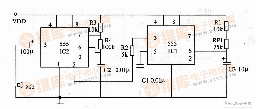
Audio circuit
In the figure, the illustrated parameters can be used to determine the oscillation frequency of the two oscillators.

When RP1, when the resistance of potentiometer RP1 changes from 0 to 75kΩ, the corresponding frequency is 14.4~0.9Hz.
The duty cycle of the oscillating waveform is determined by the formula D=t/T, so the maximum duty factor of the first-order oscillating waveform is 47%. IC2 is controlled by the low frequency square wave of IC1. When the output square wave of IC1 is low, the oscillation frequency of IC2 becomes low; when the output of IC1 is high, the oscillation frequency of IC2 becomes high, and a rhythmic sound is emitted from the speaker. Changing the time constant of R3, R4, and C2 will also change the acoustic frequency of the output.
The 1U Brush Cable Management Panel mounts to a standard 19" rack to organize cables while keeping dust and dirt out of the rack. Constructed of high-quality steel with high-density nylon bristles, the 1U brush plate creates a clean looking point of entry and offers cable separation for simple cable organization. The brush panel also promotes proper airflow through the rack by closing off open spaces between equipment, this cable organizer comes complete with 2 sets of rack screws for easy installation.
Brush Type Cable Management,Brush Cable Management,1u brush panel,1U Cable Management
NINGBO UONICORE ELECTRONICS CO., LTD , https://www.uonicore.com