![<?echo $_SERVER['SERVER_NAME'];?>](/template/twentyseventeen/skin/images/header.jpg)
This article guides reading
As an Internet of Things ecosystem, AWorks requires a large number of signal (temperature, voltage, current...) acquisition modules to realize the perception of the external world. To this end, ZLG Zhiyuan Electronics has independently developed a series of hardware modules. This article describes the TPS0xR/T series of temperature detection modules and EMM400x series of energy efficiency detection modules. This article is "Programs and Interfaces for AWorks Programming (on)" Part III Software - Chapter 14 - Sections 1-2: Temperature Detection Module - TPS0xR / T and energy efficiency detection module EMM400x.
This chapter guides reading
As the IoT IoT ecosystem, the AWorks platform requires a large number of basic hardware modules to realize the perception of the external world, such as temperature acquisition, voltage and current acquisition, and so on. To this end, after long-term research, analysis and development, ZLG has introduced a series of completely independent research and development of common modules, including: temperature detection module, energy efficiency detection module, signal conditioning module. In practical applications, these signal acquisition modules need to be connected to the controller through some interface (for example: I2C, SPI, UART, etc.). When the number of modules used by the application is too much, the interface provided by the MCU controller may not be sufficient. Based on this ZLG also introduced a series of interface expansion modules that can extend the MCU interface.
For ease of use, the user can quickly apply the module to the actual project. ZLG has introduced a series of modules that provide the corresponding AWorks drivers so that users can skip the steps of starting development from registers and use these modules directly based on the interface. Different types of modules are used in a similar way. Therefore, only one typical module from each type of module is used for introduction. Their models are: TPS02R (temperature detection module), EMM400 (energy efficiency detection module), TPS08U (signal conditioning module) and
RTM11AT (Interface Expansion Module).
14.1 Temperature Detection Module - TPS0xR/T
The TPS0xR/T series temperature detection module is a well-designed isolation temperature measurement module from ZLG Zhiyuan Electronics. The TPS0xR/T contains a series of models. The model is based on the number of channels, the communication interface (I2C or SPI) and the supported sensor type (PT100 RTD or thermocouple). The selection table is shown in Table 14.1.
Table 14.1 TPS0xR/T Series Thermal Resistance, Thermocouple Temperature Detection Module
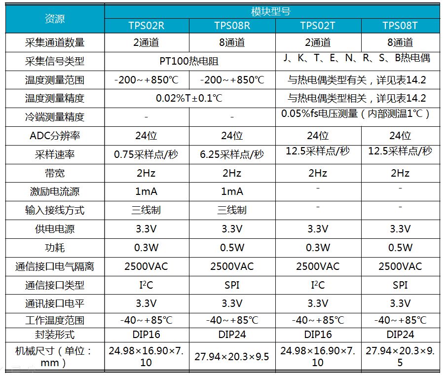
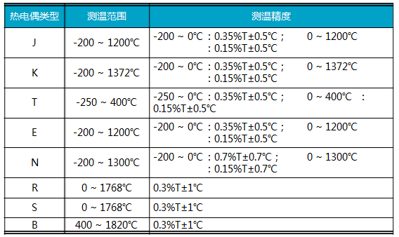
Table 14.2 TPS0xT Temperature Range and Accuracy with Thermocouple Types
In AWorks, the usage of TPS0xR/T series modules are similar. This section will use the TPS02R module as an example to explain how to use this series of temperature detection modules in AWorks.
14.1.1 Introduction to TPS02R
The TPS02R module is an isolated thermal resistance temperature measurement module. Just connect the PT100 thermal resistor to complete the temperature acquisition and use the standard I2C interface to directly output temperature data in °C. The built-in electrical isolation of the module guarantees uninterrupted measurement results. With an ultra-small volume design, it is easier to integrate into various temperature measuring devices.
1. Product Features
TPS02R mainly has the following features:
Two-channel PT100 thermal resistance measurement, I2C communication interface;
-200 °C ~ 850 °C temperature range;
0.01 °C temperature resolution, ± (0.02% +0.1 °C) temperature error;
Isolation pressure 2500VRMS;
Working environment -40°C ~ +85°C;
3.3V supply voltage
Temperature alarm output;
Isolation pressure 2500VRMS.
Pin distribution
The TPS02R has 12 external pins. See Figure 14.1 for pin definitions and Table 14.3 for pin functional descriptions.
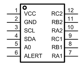
Figure 14.1 TPS02R Pin Diagram
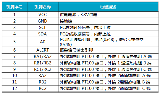
Table 14.3 TPS02R Pin Function Table
The communication interface of TPS02R is a standard I2C interface, and the master chip can read the temperature values ​​of the two channels through the I2C bus. In particular, the A0 (#5) pin determines the module's 7-bit I2C slave address. If the pin is grounded, the slave address is 0x48; if the pin is connected to VCC or directly floating, the slave address is 0x49.
The ALERT pin of the TPS02R is an alarm signal output pin. The ALERT pin can be associated with a temperature value. When the temperature status of the channel is abnormal (when the upper limit or lower limit temperature value is exceeded), the alarm is sent and the master is notified of the time.
3. Application circuit
The TPS02R is a two-channel thermal resistance measurement module, where RA1, RB1, and RC1 are the interfaces of channel 1, and RA2, RB2, and RC2 are the interfaces of channel 2. If the user only uses one channel, such as channel 1, only the relevant pins of channel 1 (RA1, RB1, and RC1) need to be connected to the one-way three-wire RTD PT100. For unused channels 2, to avoid affecting the acquisition of channel 1, the three pins RA2, RB2, and RC2 should be shorted. See Figure 14.2(a) for details. Channel 2 can also be used instead of channel 1, as shown in Figure 14.2(b).
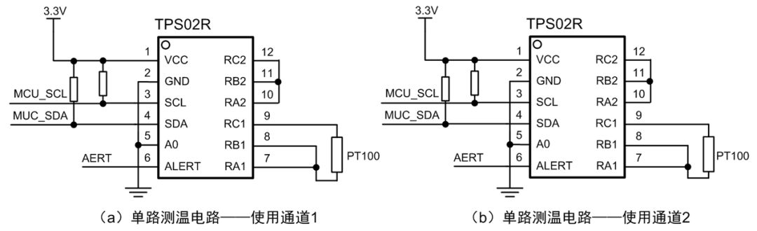
Figure 14.2 Single Temperature Measurement Circuit
If the user uses two channels, the corresponding application circuit is shown in Figure 14.3. This circuit is a typical two-circuit temperature measurement circuit in which RA1, RB1, and RC1 are connected to a three-wire RTD PT100, and RA2, RB2, and RC2 are connected to the other three-wire RTD PT100.
Note that in typical application circuits, the A0 pin is directly connected to ground. Therefore, the module's 7-bit I2C slave address is 0x48.
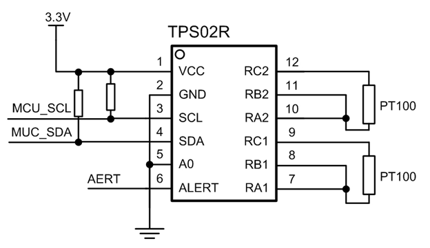
Figure 14.3 Dual Temperature Measurement Circuit
14.1.2 Adding TPS02R Hardware Devices
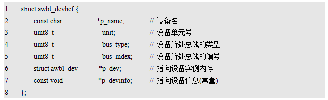
According to the introduction of AWbus-lite, in AWorks, all hardware devices are managed by AWbus-lite. Before using a hardware device, the hardware device must be added to the hardware device list (see Listing 12.1). A hardware device is described by a struct awbl_devhcf structure constant. Review the definition of this type. See Listing 14.1 for details.
Listing 14.1 struct awbl_devhcf type definition (awbus_lite.h)
Device name
The device name is often the same as the driver name. The driver name of TPS02R is defined in the corresponding driver header file (awbl_tps02r.h). See Listing 14.2 for details.
Listing 14.2 TPS02R Driver Name Definition (awbl_tps02r.h)

Based on this, the device name should be: AWBL_TPS02R_NAME.
2. Equipment unit number
The device unit number is used to distinguish several identical hardware devices in the system. Their device names are the same and multiplex the same driver. If the current system uses only one TPS02R module, set it to 0.
3 device parent bus type
The communication interface of TPS02R is I2C, which is an I2C slave device. Its corresponding parent bus type is: AWBL_BUSID_I2C.
4 device parent bus number
The number of the device parent bus depends on which I2C bus the actual TPS02R I2C interface is connected to. The number of each I2C bus is defined in the aw_prj_params.h file. For example, in the i.MX28x hardware platform, there are three defaults. I2C bus: Hardware I2C0, I2C1, and GPIO analog I2C. Their corresponding bus numbers are 0, 1, 2 respectively. See Listing 14.3 for details.
Listing 14.3 I2C Bus Numbering Definition

If the TPS02R is connected to a GPIO analog I2C0, the device's parent bus number is: GPIO_I2C0_BUSID.
5. Equipment Example
In the awbl_tps02r.h file, the device type of the TPS02R is defined as: struct awbl_tps02r_dev. Based on this type, you can define a device instance. See Listing 14.4 for details.
Listing 14.4 defines the TPS02R device instance

Among them, the address of __g_tps02r_dev_0 can be used as the value of p_dev.
6. Equipment Information
In the awbl_tps02r.h file, the device information type defined for the TPS02R is: struct awbl_tps02r_devinfo, and its definition is described in Listing 14.5.
Listing 14.5 struct awbl_tps02r_devinfo Definition
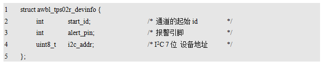
The start_id indicates the initial id of the sensor channel allocated for the TPS02R device. To distinguish each sensor channel, you need to assign an id for each channel. For a specific sensor, the number of sensor channels that can be provided for the system is fixed. For example, the TPS02R can provide two temperature sensor channels for the system: PT100 channel 1 and PT100 channel 2. For the sake of simplicity, the user only needs to provide one channel initial id, and other channels are sequentially numbered in sequence. The two temperature channel IDs of the TPS02R are start_id and (start_id+1). If the start_id is 1, two channels of the TPS02R are occupied. The IDs are 1 and 2. The channel ID is used to distinguish all sensor channels in the system, and the sensor channels occupied by different sensor devices must be different. In order to facilitate the management of the sensor channel id and avoid duplicate allocation, the initial id of a series of sensor channels provided by the device is uniformly defined.
In the aw_pri_params.h file, for example, the starting id of the 2-channel sensor channels provided by the TPS02R can be defined as:

Based on this, the value of start_id can be set to
SENSOR_TPS02R_0_START_ID, if you need to modify the initial id, you only need to modify the corresponding macro value.
Alert_pin indicates the master pin number connected to the ALERT pin of the TPS02R. TPS02R has a temperature alarm output function, ALERT pin can be associated with a certain temperature, when the temperature exceeds the upper limit temperature or below the lower limit temperature, TPS02R will notify the main control through the ALERT pin, so that the main control can be processed in time Alarm event. If the PIO2_14 of the i.MX28x is connected to the ALERT pin of the TPS02R, the value of the alert_pin should be set to PIO2_14. In particular, if the user does not need to use the alarm function, just set the alert_pin to -1.
I2c_addr indicates the 7-bit I2C slave address of TPS02R. This value is related to the specific application circuit. In a typical application circuit, the A0 pin of TPS02R is connected to GND. Therefore, if a typical application circuit is used directly, the slave address is 0x48. In this case, set i2c_addr to 0x48. can.
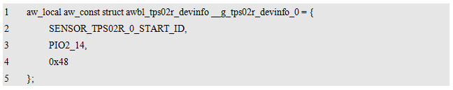
Based on the above information, complete device information can be defined. For an example, see Listing 14.6.
Listing 14.6 TPS02R Device Information Definition Example
A description of the TPS02R hardware device can be completed by synthesizing the above device name, device unit number, parent bus type, parent bus number, device instance, and device information. The definition is shown in Listing 14.7.
Listing 14.7 Detailed definition of the hardware device macro for the TPS02R (awbl_hwconf_tps02r_0.h)
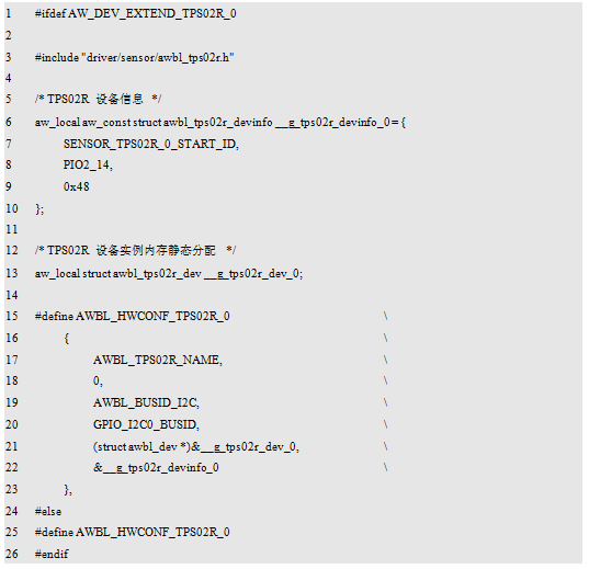
Among them, the hardware device macro is defined:
AWBL_HWCONF_TPS02R_0, for the convenience of cropping, uses an enable macro AW_DEV_EXTEND_TPS02R_0 to control its specific content. Only when the enable macro is effectively defined, AWBL_HWCONF_TPS02R_0 represents a valid hardware device. In the hardware device list, add this macro to complete the device addition. See Listing 14.8 for details.
Listing 14.8 Adding a Device to the Hardware Device List

In fact, in the list of hardware devices for template engineering,
The AWBL_HWCONF_TPS02R_0 macro has been added by default, and at the same time, the file that defines this macro
(awbl_hwconf_tps02r_0.h) is also provided as a configuration template in a template project, without the user having to develop it from scratch.
14.1.3 Using the TPS02R Module
TPS02R can collect two temperature, so it can provide two temperature sensor channels for the system. When adding a TPS02R device, the initial id of the sensor channel provided by the TPS02R is defined as: SENSOR_TPS02R_0_START_ID, which is 1 by default. This shows that the TPS02R provides the sensor channel resources for the system as detailed in Table 14.4.
Table 14.4 Sensor Channel Resources Provided by the TPS02R to the System
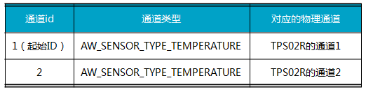
Based on this, the application program can use the “universal sensor interface†(see Table 6.6 for details) to operate sensor channels with ids 1 and 2 to obtain temperature values ​​from these channels. For example, read the temperature data of TPS02R channel 1 (id 1) or channel 2 (id 2) every second and print the temperature value through the serial port. The sample program is detailed in Listing 14.9.
Listing 14.9 Sample Program Using TPS02R
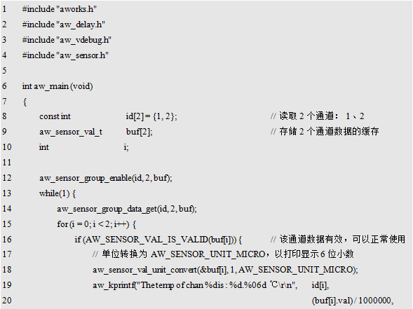
Since the TPS02R is accurate to 0.000122°C, 6 decimal places are displayed at the print temperature. To facilitate the print display, the temperature unit is converted before printing.
AW_SENSOR_UNIT_MICRO (ie: -6).
14.2 Energy Efficiency Inspection Module - EMM400x
EMM400x is a series of energy efficiency detection modules carefully designed by ZLG Zhiyuan Electronics. EMM400x contains a series of models. The model is mainly divided according to the number of channels. The selection table is shown in Table 14.5.
Table 14.5 EMM400x series energy efficiency detection module selection table
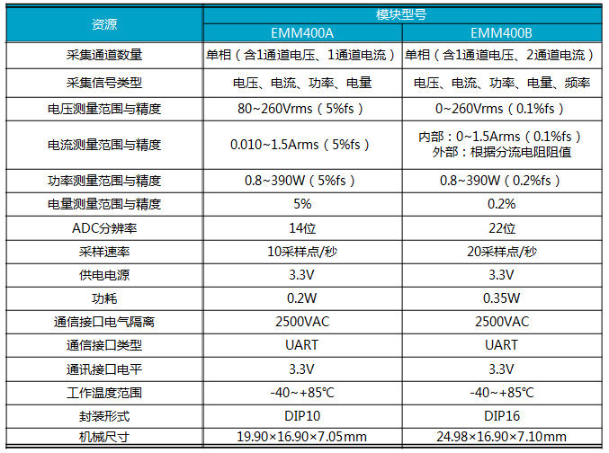
In AWorks, the usage of EMM400x series modules are similar. This section will use EMM400A module as an example to explain how to use this series of energy efficiency detection modules in AWorks.
14.2.1 Introduction to EMM400A
EMM400A is an energy efficiency management module launched by ZLG Zhiyuan Electronics for board-level circuits, integrating a power measuring unit, a DC-DC isolated power supply, and a communication signal isolation circuit, which can independently complete the measurement of the mains voltage, current, active power, and power. The main equipment effectively controls the power equipment. Accuracy of up to 2%, built-in 2500V electrical isolation circuit, can effectively isolate the mains and board within the weak. This module uses an ultra-small size design to provide users with the most convenient energy efficiency management solution while ensuring a compact PCB. The product does not require peripheral components, it is easy to use and the connection method is simple. Single-serial communication used by the communication method, users only need to receive data, do not need to send data to operate the module register, which greatly saves the program use of resources.
1. Product Features
Calibration-free single-phase energy metering
Data transmission mode: serial port, baud rate 4800bps;
Effective input voltage: 80~260Vrms, accuracy 2%;
Effective input current: 0.010~1.5Arms, accuracy 2%;
Input active power: 0.8~390W, accuracy 2%, absolute error 0.06W;
Isolated pressure 2500VDC;
Operating temperature: -40°C~+85°C.
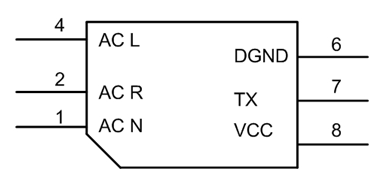
Figure 14.4 EMM400A pin definition
Pin distribution
The EMM400 is a DIP-6 package. See Figure 14.4 for pin definitions and Table 14.6 for pin functional descriptions.
Table 14.6 EMM400A Pin Functional Description

3. Application circuit
The external wiring of EMM400A is detailed in Figure 14.5. No external components are needed, only wiring according to the recommended circuit: 1 foot to the neutral wire of the power grid, 2 feet to the low end of the load, 4 feet to the live wire of the power grid; 6 feet to the digital ground of the MCU, 7 feet to the MCU's RX Receive pin, 8-pin 3.3V power input.
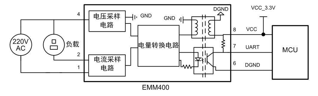
Figure 14.5 EMM400A Peripheral Circuit Connection
In the use of the recommended circuit, the lap of the external circuit should pay attention to the safety of the wiring on the high-voltage side, and the high-end and low-end of the high-voltage line should preferably meet the recommended clearance on EN60950, that is at least 3mm away; at the same time, the PCB line should be designed As wide as possible, as short as possible, making the line impedance as small as possible, reducing the line loss.
4. Communication method
The EMM400 is a single-phase multi-function metering module that provides high-frequency pulses for energy metering. The EMM400 uses a serial port for communication. Users can directly read voltage, current, and active power related calculation parameters such as calibration coefficients and signal cycles through the serial port.
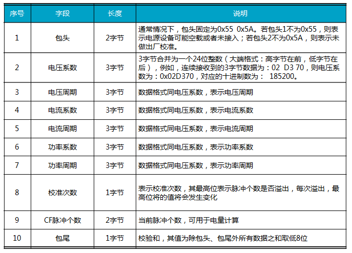
Serial-related parameters are fixed at 4800bps, 8 data bits, 1 even parity, and 1 stop bit. After the EMM400 is powered on, data packets including voltage coefficients, voltage cycles, current coefficients, current cycles, power coefficients, power cycles, calibration times, and CF pulse numbers are automatically transmitted through the serial port every 50 ms. A packet is fixed at 24 bytes, and the packet format is detailed in Table 14.7.
Table 14.7 EMM400 Packet Format
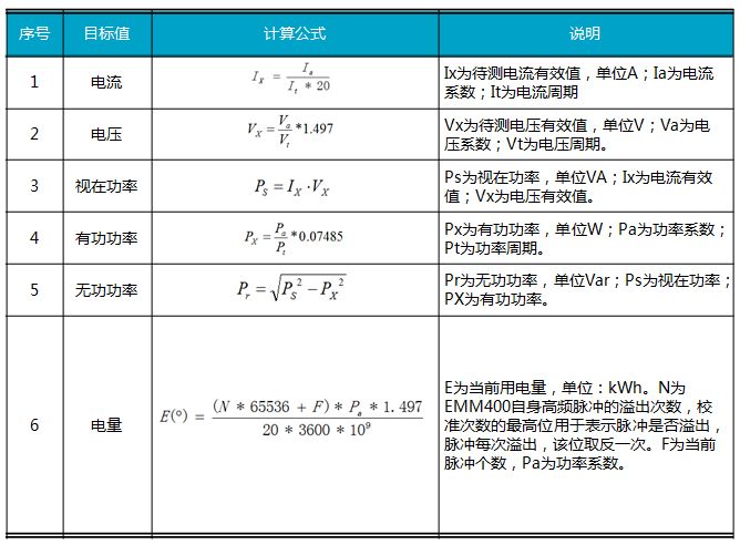
After obtaining each data, the current, voltage, apparent power, active power, reactive power, and power can be calculated by the formula. The calculation formulas and descriptions are detailed in Table 14.8.
Table 14.8 EMM400 related data calculation formula
The above communication protocols and calculation formulas are only for understanding. In practical applications, AWorks has provided the driver of EMM400, and users do not need to obtain various calculation parameters through the serial port and then enter the calculations in the formula. Users can directly use the universal sensor interface to obtain current, voltage, and vision. In power, active power, reactive power, power, and other data.
14.2.2 Adding EMM400 Hardware Devices
In AWorks, hardware devices are uniformly managed by AWBus-lite. Adding a hardware device to AWBus-lite requires confirmation of 6 points of information: device name, device unit number, parent bus type, parent bus number, device instance, and device information.
Device name
The device name is often the same as the driver name. The EMM400 driver name is defined in the EMM400 driver header file (awbl_emm400.h). See Listing 14.10 for details.
Listing 14.10 EMM400 Driver Name Definition (awbl_emm400.h)

Based on this, the device name should be:
AWBL_EMM400_NAME.
2. Equipment unit number
The device unit number is used to distinguish several identical hardware devices in the system. Their device names are the same and multiplex the same driver. If the system uses only one EMM400, set it to 0.
3 device parent bus type
The EMM400 module needs to communicate through the serial port. In the current system, the serial port is only a simple data transmission module and is not considered as an independent bus type. Therefore, the EMM400 is regarded as directly controlled by the CPU and is hung on the PLB bus. Based on this, the value of bus_type is AWBL_BUSID_PLB.
4 device parent bus number
The EMM400 device is attached to the PLB bus. The system has only one PLB bus. The value of bus_index can only be 0.
5. Equipment Example
In the awbl_emm400.h file, the device type of the EMM400 is defined as: struct awbl_emm400_dev. Based on this type, you can define a device instance. See Listing 14.11 for details.
Listing 14.11 Defining EMM400 Device Examples

Among them, the address of __g_emm400_dev0 can be used as the value of p_dev.
6. Equipment Information
The specific type of device information is defined by the device driver. In the awbl_emm400.h file, the device information type of the EMM400 is defined as: awbl_emm400_devinfo_t, the definition of which is described in Listing 14.12.
Listing 14.12 Device Information Type (awbl_emm400.h)
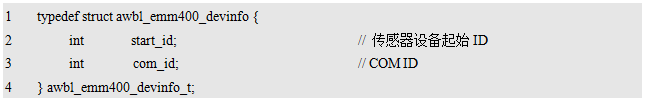
Among them, start_id represents the initial id of the sensor channel allocated for the EMM400A device. The EMM400 can provide six channels of sensor channels for the system. They are used to obtain the voltage rms value, current rms value, apparent power, active power, reactive power, and power consumption in order. The starting id identifies the starting id of the 6 channels. The id range occupied by the EMM400 is: start_id ~ (start_id + 6 - 1). For example, if the start_id is 3, the occupied id ranges from 3 to 8. In order to facilitate the management of the sensor channel id, the starting id of a series of sensor channels provided by the device is uniformly defined in aw_pri_params.h. For example, the initial id of the 6 sensor channels provided by the EMM400 may be defined as:

Based on this, the value of start_id can be set to
SENSOR_EMM400_0_START_ID, if you need to modify the initial id, you only need to modify the corresponding macro value.
Com_id is the serial port number that communicates with the EMM400 module. The available serial port number is related to the specific hardware platform used. It is defined in the aw_prj_params.h file. For example, in the i.MX28x hardware platform, six serial ports are supported, including one debug serial port and five application serial ports. The serial port numbers are defined in the program listing 14.13.
Listing 14.13 Serial Port Definition
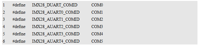
If using AUART0 to communicate with EMM400, the value of com_id is IMX28_AUART0_COMID.
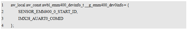
At this point, you can define complete device information. For an example, see Listing 14.14.
Listing 14.14 Sample EMM400 device information definition
A description of the EMM400 hardware device can be completed by synthesizing the above device name, device unit number, parent bus type, parent bus number, device instance, and device information. The definition is shown in Listing 14.15.
Listing 14.15 Detailed definition of EMM400 hardware device macros (awbl_hwconf_emm400_0.h)
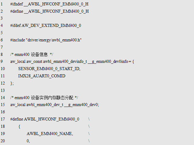
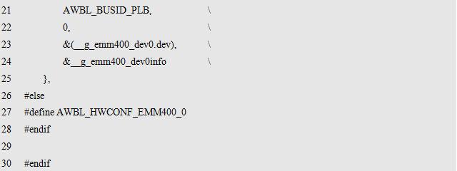
Among them, the hardware device macro is defined:
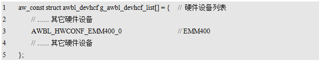
AWBL_HWCONF_EMM400_0, for ease of trimming, uses an enable macro AW_DEV_EXTEND_EMM400_0 to control its specific content. AWBL_HWCONF_EMM400_0 represents a valid hardware device only when the enable macro is effectively defined. In the hardware device list, add this macro to complete the device addition. See Listing 14.16 for details.
Program Listing 14.16 Adding Devices to the Hardware Devices List
In fact, in the list of hardware devices for template engineering,
The AWBL_HWCONF_EMM400_0 macro has been added by default and defines the macro file
(awbl_hwconf_emm400_0.h) is also provided as a configuration template in a template project, eliminating the need for users to develop their own from scratch.
14.2.3 Using the EMM400 Module
The EMM400 can collect 6 sensor signals: voltage rms, current rms, apparent power, active power, reactive power, and power usage. When adding an EMM400 device, the initial id of the sensor channel provided by the EMM400 is defined as: SENSOR_EMM400_0_START_ID, which is 3 by default. Therefore, the sensor channel resources provided by the EMM400 for the system are detailed in Table 14.9.
Table 14.9 Sensor Channel Resources Provided by the EMM400 to the System
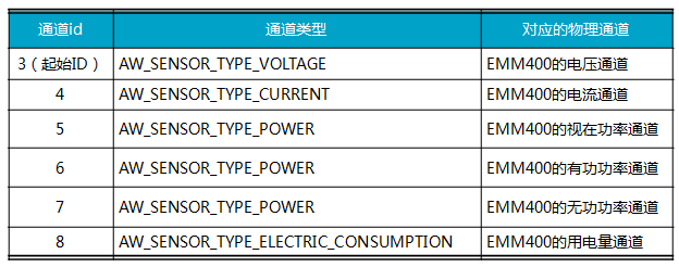
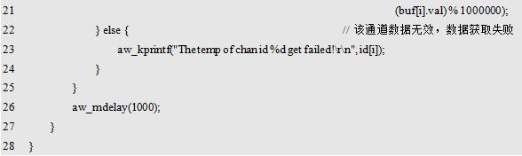
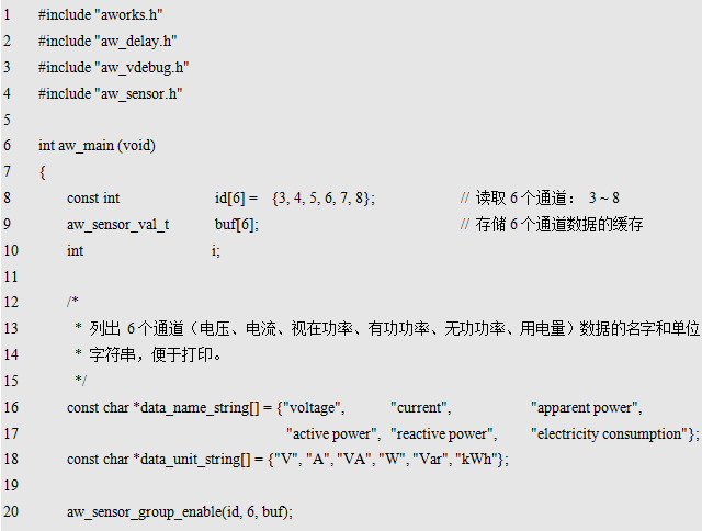
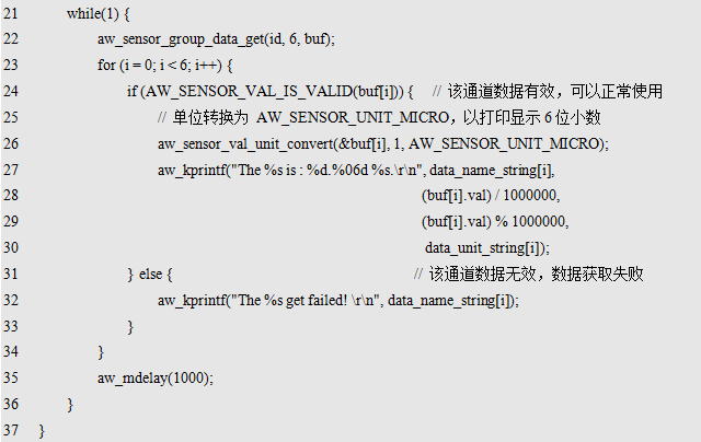
Based on this, the application program can use the “universal sensor interface†(see Table 6.6 for details) to operate sensor channels with ids of 3 to 8 to obtain corresponding sensor values ​​from these channels. For example, the value of all channels is printed once every second. For an example program, see Listing 14.17.
Listing 14.17 Sample Program Using EMM400

AC Input : 100V to 240V, DC Output: 12 volt at 2 amp rating . Please refer to the ASIN :B0746GCGQ8 if u need 10 units.
Type : Regulated Switching Power Supply with 2.1mm x 5.5mm plug , center positiveManufactured with high quality material and built-in protection of over current, over voltage, short circuits .
COMPACT DESIGN and LOW CONSUMPTION makes it ideal for taking around and using at home.
12v wall charger,12v switching adapter,(12V/2A) Switching Mode Power Adapter Wall Charger,12V 2A Power Supply Adapter,12 Volt 2 Amp Power Adapter,12V 3A Power Supply Adapter,12v3a wall charger
Shenzhen Waweis Technology Co., Ltd. , https://www.laptopsasdapter.com