![<?echo $_SERVER['SERVER_NAME'];?>](/template/twentyseventeen/skin/images/header.jpg)
In recent years, with the continuous advancement of technologies such as wireless communication, microelectronics technology, sensor technology and embedded computing, the development of low-cost, low-power wireless sensor network WSN (Wireless Sensor Network) has been promoted, making WSN active today. Research area [1]. The WSN consists of a large number of inexpensive micro-sensor nodes deployed in the monitoring area, and a multi-hop self-organizing network system formed by wireless communication, the purpose of which is to cooperatively perceive, collect and process the information of the sensing objects in the network coverage area, and Sent to the observer [2]. Wireless sensor networks have broad application prospects in both military and civilian applications. This paper introduces WSN into the bicycle anti-theft system of the community, and gives a design scheme of a community bicycle anti-theft system based on WSN. It provides guarantee for the management of community bicycles, especially theft prevention.
This article refers to the address: http://
1 system plan
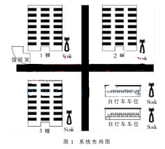
Residential areas usually plan to park two-wheeled vehicles such as bicycles in the middle of a residential building or in a concentrated area. As shown in Figure 1, bicycles are usually placed in designated parking spaces. In order to enhance the management of bicycles, WSN technology is introduced in this paper. The anti-theft system consists of two parts: information collection and alarm prompt.
(1) Information collection
First, each bicycle is equipped with an electronic lock with a unique ID as the identification of the bicycle in the cell. The electronic lock has a WSN node function, can detect whether the line is disconnected, the battery power, and has wireless communication capability, and can send the detected information to the observation point in a multi-hop manner. In order to facilitate the collection of information and provide reference information for the observers, the sink nodes are deployed at designated locations (such as carports, residential buildings, and streetlight poles), as shown in the Sink device of Figure 1. Different from the traditional WSN, the location of the sink node is not random, and its deployment should take into account factors such as the size of the bicycle parking area of ​​the cell and the layout of the cell. The sink node receives the information of the sensor node and forwards it to the observer.
(2) Alarm prompt
The observatory is set up in the duty room, as shown in Figure 1. The monitoring software running on the PC manages the information collected by the WSN. The monitoring software can display the approximate position of the bicycle in the cell, display the battery power of the electronic lock, prompt to replace the electronic lock battery, prompt the electronic lock to open violently, and prompt the bicycle to cross the border.
After being prompted by the monitoring system, the on-duty personnel can quickly take corresponding actions to avoid bicycle theft.
2 system hardware design
The core of the hardware design of the community bicycle anti-theft system is the WSN node design. According to the task division undertaken in the system, the WSN node can be divided into a general sensing node and a sink node. But these two types of nodes only differ in software functionality, and the hardware design is not fundamentally different.
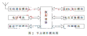
In this paper, the electronic lock and Sink node are divided into six hardware modules, as shown in Figure 2, with the microcontroller as the core, the wireless communication module, power module, disconnection detection module, LED indication module, voltage acquisition module, and buttons are extended. Module.
2.1 Microcontroller
This article uses ATmega128L as the main processor. The ATmega128L is an 8-bit low-power CMOS microprocessor based on the AVR RISC architecture [3]. The data throughput rate is up to 1 MIPS/MHz, which alleviates the contradiction between power consumption and processor. The chip comes with 128 KB of programmable Flash, which eliminates the need for external memory in this application. In addition, ATmega128L has a wealth of interface resources (such as SPI, USART, TWI, ADC, etc.), which provides important support for this application.
2.2 Wireless Communication Module
The wireless communication module adopts CC1000, which is an ideal UHF single-chip transceiver communication chip manufactured by Chipcon's SmartRF technology in 0.35 μm CMOS process [4]. Its operating frequency bands are 315 MHz, 868 MHz and 915 MHz, but the CC1000 is easily programmed to operate in the 300 MHz to 1 000 MHz range. It features low voltage (2.3 V to 3.6 V), very low power consumption, programmable output power (-20 dBm to 10 dBm), high sensitivity (typically -109 dBm), small size (TSSOP-28 package), integration Features such as a bit synchronizer. Its FSK data rate can reach 72.8 kb/s, with programmable frequency capability of 250 Hz step, suitable for frequency hopping protocol; the main working parameters can be changed through serial bus interface programming, and the use is very flexible.
The ATmega128L operates the CC1000 chip through the PCLK, PDATA, and PALE three-wire digital serial interface to control its operating status and parameter settings. DIO is a bidirectional pin for data exchange between CC1000 and ATmega128L. The data exchange clock is always provided by the DCLK of CC1000, that is, CC1000 is always in the master state [5].
2.3 disconnection alarm module
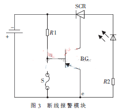
The disconnection alarm module is a component of the electronic lock. The basic principle is shown in Figure 3. In the alarm state, the base bias voltage of the BG is short-circuited to the ground via the warning line S, and the BG does not work. In case of scam, S is disconnected, BG immediately works, SCR is turned on, and the LED is lit. Micro-control ATmega128L detects the voltage of two points b and e through the voltage detection module to determine the state of the electronic lock.
2.4 Other modules
The power module supplies power to the ATmega128L, CC1000, and wire break alarm modules. The voltage detection module has two functions: one is to detect the power supply voltage to determine whether to replace the battery; the other is to detect the voltage of the disconnection alarm module b, e at two points to determine whether the electronic lock is violently turned on. The LED indication module is used to indicate the running status of the WSN node and serve the debugging. The button module is used for password setting and status setting of the electronic lock.
In order to achieve the goal of energy saving, the hardware design not only considers several low-power processing modes of the processor, but also designs an analog switch. When the electronic lock is in the non-protection mode and is turned on, the switch can be exposed for the user to turn off the power. ,Reduce energy consumption.
3 system software design
There are two main parts of the community bicycle anti-theft system software: one is the software running on the WSN node, and the other is the monitoring software running on the PC. WSN node software is information sensing and communication protocol. The following is discussed from three aspects: network topology, communication protocol and monitoring software.
3.1 Network Topology
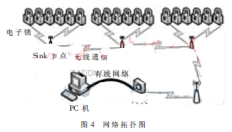
Because the area where the bicycle is parked in the community is relatively regular, the bicycles are placed relatively neatly, so the cluster-shaped tree topology shown in Fig. 4 is used in this paper. The carport area is divided into several zones, each zone forms a cluster, and the Sink node is used as the cluster head. The electronic lock node and the cluster head node form a star network, and the cluster head gathers information to be forwarded to the PC of the observation station through the Sink node. Machine for analysis and processing of monitoring software.
The ID of the electronic lock and Sink node is represented by a 16-bit binary number, which is the unique identifier of the node. The network address of the electronic lock and the Sink node is also represented by a 16-bit binary number, which can be divided into a cluster head number and a node number, each occupying 8 bits, and the network address is formed in the networking phase. The purpose of dividing the network address into the cluster head number and the node number is to filter the message. After receiving a packet, the node matches the cluster head number and the node number with its own network address. If the node is different, the packet can be deleted directly, which reduces the energy consumption caused by packet forwarding.
3.2 Communication protocol design
The deployment of the Sink node in the community bicycle anti-theft system is fixed, and when the bicycle is placed in the carport, which carport is placed, which position in the carport is uncertain, that is, the entry of the electronic lock node is random. Therefore, the operation of the communication protocol [6] is divided into two phases: the main chain network networking phase and the information sensing phase.
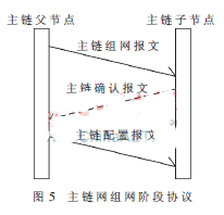
(1) Main chain network networking phase agreement
After the Sink node is deployed in a predetermined location, as shown in FIG. 4, the network includes a gateway node connected to the monitoring host, a plurality of Sink nodes, and some electronic lock sensor nodes. The gateway node is the originator of the route and the collector of the data. After the power-on is initialized, the gateway node sends a network packet, as shown in Figure 5, and advertises its own network address and synchronization time list. After receiving the network packet, the gateway neighboring node sends an acknowledgment packet according to the synchronization time list, and confirms that the packet contains its own ID. After receiving the acknowledgement packet, the gateway node sends a configuration packet to the neighboring node. The configuration packet contains the network address assigned by the gateway node to the neighboring node. In this way, the gateway node establishes a parent-child hierarchy relationship with the neighbor nodes. The child node that obtained the network address advertises the network packet and repeats it to establish the backbone network topology.
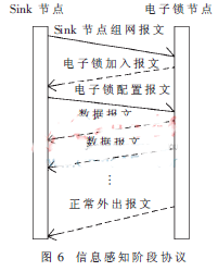
(2) Information Awareness Phase Agreement
After the main chain network topology is established, the electronic lock node randomly enters the information aware area. The network enters the information sensing stage, and the interaction process between the electronic lock node and the Sink node at this stage is as shown in FIG. 6. The Sink node periodically sends the network packet according to its own timing list. After the electronic lock that enters the Sink node detection area is set to the protection state, it will continue to listen to the network packet before the network address is obtained. After receiving the networking packet of the sink node, the electronic lock node responds to the electronic lock to join the packet according to the synchronization time list indicated in the packet, and the packet contains the ID number of the electronic lock. After receiving the electronic lock join message, the Sink node sends a configuration packet to the electronic lock node to allocate a network address for the electronic lock. After the electronic lock has the network address, it will periodically send the collected information to the Sink node and forward it to the observatory monitoring computer layer by layer. If the user needs to use the bicycle to go out normally, enter the correct password. After the electronic lock is normally turned on, the electronic lock sends a normal leave message to the Sink node, and then enters the sleep state.
3.3 Monitoring software design
The data message sent by the electronic lock to the Sink node mainly includes a disconnection alarm state, a normal outgoing state, a battery voltage value, and a network address, wherein the network address includes the cluster head number of the electronic lock. The monitoring software running on the PC collects, analyzes and processes the information to achieve the purpose of monitoring the community bicycle. The monitoring software is developed based on VC and SQL Server platform, and realizes functions such as cross-border alarm, disconnection alarm, and electronic lock battery replacement prompt.
After the system is initialized, the monitoring program starts two threads of Socket data receiving and data processing, and completes data acquisition and data processing functions respectively. Two threads use the database as the medium for data exchange to synchronize database access with semaphores.
The flow of the Socket data receiving thread is shown in Figure 7. After the thread is initialized, the Socket listener is started first, and then the networking command is sent to the gateway to establish the main chain network topology. The thread listens to the Socket port, receives the data packet from the gateway, parses the data information sensed by the WSN from the data packet, and writes the data information into the database table. The data processing thread needs to be synchronized with the semaphore before accessing the database. If the thread detects the termination thread signal sent by the main process, the thread will release the occupied resources and end itself.
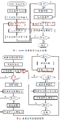
The execution flow of the data processing thread is shown in Figure 8. The data processing thread uses the database as the data source. Before accessing the database, the semaphore is synchronized with the Socket thread. After obtaining the access rights of the database, the data processing thread performs three queries in turn. The disconnection state has the highest priority, and the cross-border is the second. According to the result of the query, the alarm or prompt processing is performed, and the thread itself is terminated until the thread end flag set by the process is detected.
The system is a community bicycle management system based on wireless sensor networks. The system design combines the current status of community bicycle management and the development status of WSN technology. The ATmega128L microcontroller and CC1000 wireless chip technology are combined. In addition to the mechanical structure of the electronic lock, the laboratory model of the electronic lock node and Sink node is completed. design. Experiments show that, according to the information detected by the node, the monitoring program can correctly analyze and display the status of the electronic lock node entering, crossing, disconnecting, and leaving normally. When the boundary is crossed or disconnected, the monitoring software issues an alarm to remind the security personnel to pay attention. The effect of the model system. In order to verify the stability of the communication protocol in multiple nodes, a simulation experiment was performed based on the NS2 platform [7]. When the number of nodes reached 1 000, the protocol still worked well.
The hardware solution selected in this paper has the characteristics of low cost and low energy consumption. The designed communication protocol is simple, but it has good stability and good practical value.
LED5050 strip light of the lamp as a light source is SMD 5050led to FPC board as the carrier circuit in series with the appropriate current limiting resistor design and production of decorative lighting. With high brightness, soft, flexible, you may need to cut to length, etc.
SMD5050 LED Strip Light of the light source LED5050 lamp beads, it means that the length of LED components is 5.0mm, width is 5.0mm, the industry referred to 5050. SMD chip type genus, the carrier is a soft FPC board. That flexible circuit boards, most of the width 10MM, thickness of less than 1MM. Each FPC factory length of 0.5 meters. Can be two or several mutually welded. Produce a good Smd5050 Led Strip Light of the length of the factory 5M roll, anti-static disc and anti-static bag, portable and easy to transport.


SMD5050 LED Strip Light can be classified from the following aspects:
1. Color: FPC main color yellow board, whiteboard, blackboard, can be customized. SMD5050 Led Strip Light luminous colors: white, warm white, red, yellow, blue, green, purple, colorful, full-color, Symphony.
2. Waterproof: lights due to apply to a different location, water level is divided into not waterproof, Epoxy waterproof, waterproof casing, plastic irrigation water.
3. Lamp beads: on the FPC can be attached to many LED5050 lamp beads, so the per meter FPC, lamp beads per meter 30 lights, 60 lights per meter, 120 lights per meter three general to apply to different brightness requirements The place.
We focus on LED area, is a high-tech lighting enterprise deal in develop, produce and sales.
Owns DIP LED,SMD LED professional production lines and SMD5050 LED Strip Light lines, the produce volume per month for DIP LED,SMD LED is 50 million pieces, for SMD5050 LED Strip Light is 500 thousands meters, for LED flexible strip light for car is about 200 thousands pairs, for LED tube light is 50 thousands pieces, for LED Spotlights are 200 thousands pieces, for LED ceiling light are 50 thousands pieces.
Our R & D team can handle highly customized designs and offer OEM and ODM services.
We hope to set up a long-term partnership with you through our high quality products and our Sincere Service!

Mingxue Optoelectronics Co.,Ltd. has apply the I S O 9 0 0 1: 2 0 0 8 international quality management system certificate, we apply the CE, RoHS and SAA certificate for our led lighting product.


SMD5050 LED Strip Light
Led Strip Behind Tv,Led Office Lighting,Garage Led Strip,Yellow Led Strip
Shenzhen Mingxue Optoelectronics CO.,Ltd , https://www.mingxueled.com