![<?echo $_SERVER['SERVER_NAME'];?>](/template/twentyseventeen/skin/images/header.jpg)
Abstract: This paper discusses a circuit multi-parameter test system for real-time monitoring of vibration reliability test of automotive electrical systems. The system is based on LXI bus modular virtual instrument and LabWindows/CVI as software development platform. It effectively combines computer fault diagnosis technology to form a set of test monitoring that can independently complete remote control, test, data processing and real-time fault diagnosis. The system lays the foundation for the intelligent and traceability of the automotive electrical product testing process.
This article refers to the address: http://
1 Introduction
Due to the existence of two major excitation sources, road excitation and engine vibration, the proportion of automobile electrical and electronic system failures in the total vehicle failure is extremely high, and it is increasing year by year. Road simulation vibration testing of vehicles and their components in the test chamber is considered to be an effective means to accelerate product development and improve product quality. The traditional test process mostly uses manual guards to record relevant data. This approach has the following problems:
1. The test environment is harsh, often accompanied by noise, damp heat and other factors;
2. The time is long, and the workload of the duty guard is large;
3. Manually record data, lacking integrity and consistency;
4. The fault phenomenon is not traceable and cannot provide a sufficient basis for fault analysis;
These shortcomings have greatly affected the validity of the test and it is impossible to conduct an in-depth analysis of the test results. Due to the complex control principle of the automotive electrical system, the number of components involved is various, and the structure is various. The real-time monitoring of the test process of the vehicle electrical system by means of automated test equipment does not have an effective method. This paper focuses on the construction method of a test system for the test and fault diagnosis of vehicle electrical system applied to the "automobile electrical system reliability test bench".
2 How the monitoring system works
The automotive electrical reliability test bench uses the auxiliary test equipment to apply electrical stress and vibration stress, so that the automotive electrical system on the gantry simulates the actual working conditions of the automobile road test. "Automatic system reliability test real-time monitoring system" uses the accessible nodes in the circuit as monitoring points, and uses the data acquisition equipment to track, measure and record the voltage, current, frequency and other signals in each electrical circuit; The data is processed and analyzed in real time, faults are found in time, acoustic and photoelectric alarms are realized, and the type and location of typical faults are diagnosed.
2.1 System basic design concept
Due to the complexity of the system under test, the monitoring system is designed based on the UUT (Unit Under TEST) system planning method, as shown in Figure 1. The hardware and software design of the system is developed for the UUT type. The reason for adopting this method is:
1. The conventional electrical equipment of the automotive electrical system adopts the parallel mode. With each electrical circuit as a test unit UUT, the whole test system can be used as a circuit network system tested by multiple UUTs in parallel;
2. Some electrical equipment of automobiles have commonality in their working mode and fault form. According to their own characteristics and related standards, all UUT units can be divided into several typical categories such as lamps, motors and meters.
3. Expanding the UUT classification rather than targeting a single UUT reduces system complexity and versatility.
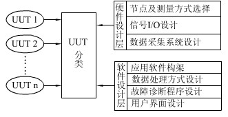
Figure 1: System basic design concept
2.2 Implementation of parameter measurement
In the reliability test, it is necessary to carry out comprehensive monitoring and accurate fault diagnosis for each electrical appliance of the system under test. The first is: First, it can obtain enough accessible test nodes from the system but can not damage the system under test. Integrity; second, the signal I/O interface must be connected reliably to withstand high-strength test stresses without failure prior to the system under test. According to the UUT type, the signal to be tested and the sampling node are determined, and the connector actually used by the automobile electrical appliance is used as a signal output interface, and the sampling connector access circuit is designed to obtain the signal required for monitoring. Figure 2 illustrates the sampling method for a resistive electrical unit. In the original state, the automotive electrical unit Rx is directly connected with the automobile wiring harness to form a working circuit, and the positive and negative loop resistances are r1 and r2, respectively, and the resistance value is unknown; the "sampling connector" including the circuit shown in the circuit is connected during the test. Circuit state parameters can be obtained without affecting the operation of the original circuit.
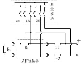
Figure 2: Resistive electrical unit monitoring principle
Construct a multi-channel data acquisition system to perform real-time measurement and data processing on electrical parameters at each node to achieve accurate fault identification and location.
3 System test instrument synthesis
The system uses a measurement platform based on the LXI (LAN eXtensions for Instrumentation) bus. LXI is a new generation of LAN-based modular platform standards for automated test systems. The LXI modular test standard combines the high performance of a GPIB instrument, the small size of a VXI/PXI card instrument, and the high-speed throughput of a LAN, taking into account instrumentation requirements such as timing, triggering, cooling, and electromagnetic compatibility. At the same time, it also has many advantages. For example, it is an open industrial standard system with backward compatibility, low instrument development cost, good interoperability and scalability. Its data transmission is free from the limitations of traditional instruments on data transmission distance and bandwidth, and can easily realize remote control of instruments and long-distance high-bandwidth data transmission. In harsh test environments, such as vibration-tested, high-noise environments, LXI has better applicability than other bus platforms due to its advantages in remote control and data transmission networks.
3. 1 main controller
As shown in Figure 3, the system uses the industrial computer as the main controller, performs module control through the LAN network, and completes the data processing, display, and storage of the system. As the main controller of the whole test system, the industrial computer is also responsible for the reliability test stress loading control.
3.2 LXI Virtual Instrument Module
1) The test host system uses the AGILENT 34980A switch/measurement unit as the hardware platform to measure and convert the side signals through the built-in digital multimeter. The test host communicates and exchanges data with the host computer via the LAN bus.
2) The multiplexer adopts the common DMM time-sharing measurement method because the signal in the system under test is mainly composed of a relatively stable DC analog signal. Two-wire measurement of 80 channels is achieved by two opto-isolated ETF switch modules.
3) The jitter measurement module is used for instantaneous monitoring to detect voltage transients in the circuit.
4) D/A conversion module D/A converter provides drive signals for the working system of the system under test, such as the voltage pulse signal required for tachometer and speedometer operation, the current signal required for fuel gauge and water temperature meter to work. The signal is controlled by the host computer and output by the D/A converter. After conditioning, it is input to the system under test through the analog I/O interface.
5) Digital Oscilloscope The digital oscilloscope communicates and exchanges data with the host computer through the LAN bus, and connects to the test host through the analog bus to share the switch module with the built-in meter. High-frequency sampling and virtual oscillography are performed on any one of the 80 measurement channels.
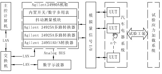
Figure 3: System hardware components
3.3 Key issues
1) Measurement of frequency signal The signal to be tested has frequency signals above 100 Hz and below 3 Hz. Since the system is a common DMM isochronous scanning measurement method, the two signals need to be measured by different sampling methods. For high frequency signals, set the system scan channel to the frequency measurement direct output. For low frequency signals below 3 Hz, the frequency channel is too low to measure directly, so a fitting method is required. This method has higher requirements on the system scanning frequency.
Nyquist theorem:
The single channel sampling rate should be determined by the upper frequency limit of the signal to be tested;
Therefore, there are:
If 80 analog channels are scanned and sampled, the total switching frequency of the switch should be greater than 480CH/s. The system design value of the clock for a single scan is 160ms, and the actual scanning frequency is 500CH/s, which realizes the measurement of low frequency signals.
2) Instantaneous monitoring realizes transient as a circuit transient phenomenon, the sampling rate of DMM time-sharing sampling method is too low to monitor this type of signal, and multi-channel parallel analog data mining leads to a large amount of data redundancy. Excessive and high system cost. The system uses the jitter measurement module to monitor the voltage hopping of each channel in real time with 32 channels of parallel digital sampling. The maximum sampling rate of single channel is 0.1μs. The monitoring voltage threshold is set to 10.5V/21V according to the test voltage of automotive electrical equipment. Optional.
4 system application software design
4.1 Software Development Environment
The system uses LabWindows/CVI as the software development platform. It has an interactive programming method and a wealth of library functions, providing an ideal software development environment for developers to establish data acquisition and process monitoring systems, and is a fast way to implement virtual instruments and networked instruments.
4.2 Multi-threading technology in test monitoring
Windows is a weak real-time operating system. It achieves preemption by thread priority, and meets the real-time requirements of most test tasks by setting the appropriate priority of the test thread. Test monitoring requires that the functions of system control, data acquisition, data display and data analysis are completed simultaneously. Using the thread pool technology in LabWindows/CVI multithreading can achieve real-time performance of the system. The interface control is used as the main thread, and the control commands are issued to other threads through the interface operation, so that the system can respond to the user operation in time; the data acquisition, real-time display, and fault diagnosis are used as auxiliary threads, and are executed synchronously with the main thread. In the auxiliary thread, the real-time display thread and the data analysis thread communicate with the data collection thread in real time through the pipeline message driving mechanism to realize data sharing between threads.
4.3 Troubleshooting Methods
According to the principle of logical recognition: the fault cause function A, the fault characteristic function X and the decision rule E satisfy the Boolean function relationship. The essence of the fault diagnosis process is to solve A from the known X and E, which is expressed in the logical language: The implementation method is to divide the system under test into six typical monitoring unit types according to UUT working characteristics, and design corresponding fault identification sub-programs for the types, including:
1. Establish a typical fault mode database with the monitoring unit type as the object, that is, construct the fault cause function A;
2. Describe the fault mode by using the measurable physical quantities I, U, f and other parameters of the circuit to construct the fault characteristic function X;
3. Based on the logical judgment, the fault decision rule E is established and converted into the corresponding fault identification subroutine.
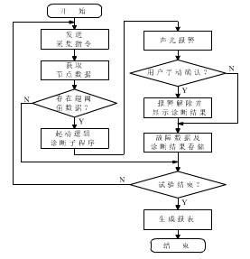
Figure 4: Troubleshooting flowchart for troubleshooting
During the running process, the system issues an acquisition instruction and retrieves the data. The data processing thread first compares the real-time data of each physical quantity to be measured with the threshold corresponding to the UUT status parameter in the threshold library. When it is found that there is a super-threshold data, it is considered that a fault has occurred and begins. The fault identification subroutine corresponding to the type of the UUT is started to perform fault diagnosis, and the diagnostic result output is output and recorded after the execution of the diagnostic subroutine. Figure 4 illustrates the troubleshooting process for the system.
4.4 System Data Management and Database
The system builds a database with Microsoft SQL Server as the underlying layer, establishes an ODBC data source through the SQL Toolkit, and performs connection and data information access operations on the database. The system configuration data can be generated by an open user interface, allowing the user to configure the system for different test subjects, thus ensuring the flexibility and versatility of the system.
5 Conclusion
The system is applied to the vibration reliability test of an automobile enterprise, and solves the problem of intelligent monitoring of the test process of the automobile electrical system. The results show that the system can correctly measure, display, record and replay the physical quantities of each test; it can diagnose and alarm the faults in real time, effectively improve the many drawbacks of the traditional test monitoring methods, and can meet the real-time requirements of the system under test. The engineering requirements for monitoring; combined with virtual instrument software development technology based on LXI bus instruments, is an effective means to build a comprehensive test and measurement system. The integration of modern test technology and computer technology makes the automatic monitoring of the reliability test of automotive electrical system become a reality, making the test process intelligent and scientific; the failure mechanism analysis of the test system, the reliability test result * price, automotive products The design and quality improvements provide a scientific basis.
The author's innovations: 1. The construction scheme of a multi-parameter test and monitoring system based on LXI bus is proposed. 2. A real-time diagnosis method for automobile electrical faults based on UUT classification is established.
When the semiconductor diode is turned on, it is equivalent to the switch closing (circuit is turned on), and when it is turned off, it is equivalent to the switch opening (circuit cut), so the diode can be used for switching, and the commonly used model is 1N4148. Since the semiconductor diode has a unidirectional conduction characteristic, the PN junction is turned on under a positive bias, and the resistance in the on state is small, about several tens to several hundreds of ohms; in the reverse bias, it is off. The resistance is very large. Generally, the silicon diode is above 10 Μ Ω, and the bismuth tube is also several tens of kilo ohms to several hundred kilo ohms. With this feature, the diode will act as a control for the current to turn on or off in the circuit, making it an ideal electronic switch.
Switching Diode,1N4148 Signal Diode,4148 Diode,1N4148 Diode
Dongguan Agertech Technology Co., Ltd. , https://www.agertechcomponents.com