![<?echo $_SERVER['SERVER_NAME'];?>](/template/twentyseventeen/skin/images/header.jpg)
Abstract: This paper introduces a wireless headset based on nRF24E1 for home TV and personal computer. It elaborates the hardware design method of wireless headset, explains the working principle of voice transmission and reception, and gives the main workflow of software design. .
This article refers to the address: http://
0 Preface
Currently, with the popularity of Interne and personal computers, people often use wired headsets for voice chat. Due to the limitations of wired headsets, people must sit in front of the computer to voice chat.
If it takes a long time, it will cause the computer to radiate to the human body, thus affecting people's health. In home TV, people usually use the built-in speaker of the TV to listen to the sound from the TV, which sometimes gives the rest of the family work and rest. Have a certain impact.
Based on these problems, this paper designs and implements a wireless headset based on nRF24E1. The design has the advantages of strong anti-interference ability, good confidentiality, good sound quality and low cost. The indoor transmission distance is about 30 meters, which reduces the radiation of the computer to the human body and does not affect the rest and work of other members of the family.
The wireless headset uses the current state-of-the-art wireless transceiver chip nRF24E1, which can realize wireless communication of voice in the world's common ISM frequency band 2. 4G ~ 2. 5GHZ.
1 nRF24E1 Introduction
The nRF24E1 chip is a wireless transceiver module with a 2. 4GHz wireless transceiver nRF2401 and an enhanced 8051 core. With a channel operation time of less than 200us and a data rate of 1Mbps, the chip does not require an external SAW filter. It is the world's first low-cost RF system-on-chip. It is internally embedded with an 8051-compatible microprocessor and a 10-bit, 9-input A/D converter that can operate stably from 1. 9V to 3. 6V. It is also embedded with a voltage regulator and VDD voltage monitoring. Device. The wireless transceiver section has the same functionality as the nRF2401. This function is initiated by the internal parallel port and the internal SPI. Each pending signal can be programmed as an interrupt for the processor or transmitted to the microprocessor via the GPIO port. The nRF24E1 chip enables wireless communication in the world's common ISM (Industrial, Scientific, and Medical) frequency bands of 2.4 to 2. 5 GHz. The transceiver part contains a frequency divider, an amplifier, a regulator and two transceiver units. The output energy, frequency band and other RF parameters can be easily programmed and adjusted through the RF register. In the transmit mode, the current consumption is only 10. 5 mA; in the receive mode, the current consumption is only 18 mA, so the power consumption is quite low.
2 Wireless headset hardware structure design
The wireless headset is mainly composed of a plug portion and a headset portion. The plug part consists mainly of two plugs and an nRF24E 1 . The two plugs are a microphone plug and a headphone plug, respectively, which are respectively inserted into the microphone jack of the computer and the headphone jack or the headphone jack of the home TV; the headset part mainly consists of a microphone, a headphone and an nRF24E1. Its hardware structure block diagram is shown in Figure 1. The wireless headset realizes two-way communication of voice through the wireless voice transceiver chip nRF24E1.
The wireless headset can send the voice of the person into the computer via the microphone; it can also send the sound of the computer or TV to the headset of the wireless headset. Whether it is sending voice to a computer or TV, or sending voice to a headset, the principle of one-way voice transmission is the same.
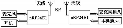
Figure 1 Wireless hardware block diagram of the wireless headset
The nRF24E1 chip has a 9-channel 10-bit ADC (Analog to Digital Converter), which has a sampling frequency of 24 bytes or 3m s for each RF (Radio Frequency) data. Audio sampling signal.
The wireless headset sends the vocal to the computer or the TV is sent and received as shown in Figure 2:
At the transmitting end, the ADC performs A/D conversion on the analog audio signal sent from the microphone; the collected digital audio signal is stored in the transmit buffer (TxBu f) opened in the microcontroller 8051 before enough RF data packets are available. After the sampled data is full, the 8051 stores the next data packet, and transfers the full data packet to the RF front end nRF2401, and transmits the data packet through the nRF2401.
The circuit of the transmitting end is shown in Figure 3. A pre-filtering amplifier circuit is required between the microphone and the ADC module of the nRF2401. It filters and amplifies the analog audio signal picked up by the microphone. The amplified analog audio signal is sent to the ADC.
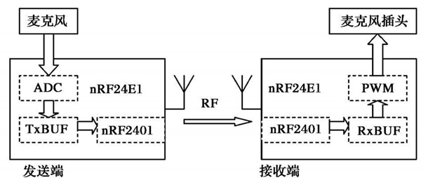
Figure 2 One-way voice transmission and reception process
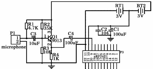
Figure 3 Voice transmission circuit diagram
At the receiving end, when the RF front end nRF2401 receives a valid data packet and the microcontroller receives an RF reception interrupt, the valid data portion of the received data packet can be separated by the FIFO of the RF front end; The separated valid data portion is stored in the receive buffer (RxBuf) in the 8051; the voice signal in the receive buffer is output as a PWM signal; the PWM output is driven by the 8-bit PWM engine, and no microcontroller sharing is required. Processing the task; finally the voice signal is sent out via the PWM signal.
The circuit diagram of the receiving end is shown in Figure 4. The nRF24E1 chip provides a PWM output. The PWM output signal of the nRF24E1 can be amplified by one level to obtain the desired audio analog signal.
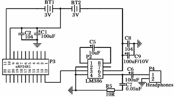
Figure 4 Receive circuit diagram of speech
3 system software design
The function of the wireless headset is to achieve two-way communication of voice. Its two parts: The workflow of the plug part and the headset part is basically the same. The workflow is as follows:
1. Power on the system and turn on the system; 2. Initialize. Initialize the 8051 timer time2, PWM output port, ADC converter, RADIO, SPI interface and wireless transceiver module nRF2401; 3. Determine whether to send a voice signal, if yes, send, then go to step 4; 4. If not When the voice is transmitted, it is judged whether or not the voice signal is to be received. If yes, receive, then proceed to step 3; 5. If there is no voice reception, proceed to step 3.
The corresponding flow chart is shown in Figure 5:
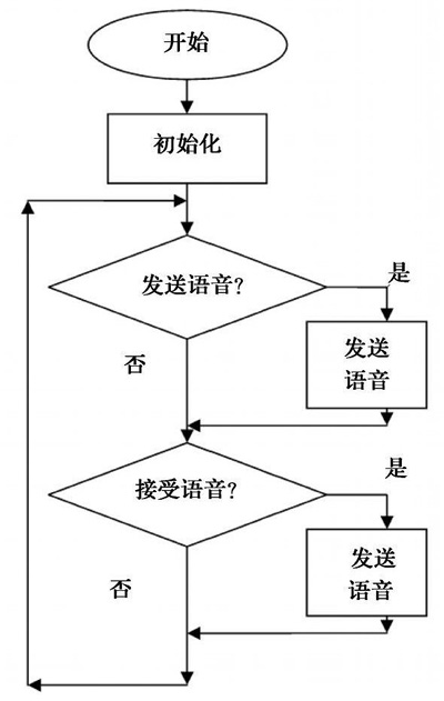
Figure 5 Work flow chart of the plug part and the headset part
Initialization is mainly to initialize the timer time2, PWM, ADC, RADIO, SPI, nRF2401. Among them, the timer t ime2 is mainly used to generate a timer interrupt trigger. In this system, the ime2 generates an interrupt every 125us, so that the system digitally samples the analog audio signal output by the microphone. The sampling frequency is 8KH. z. Initialization of the ime2 is mainly to make the ime2 normal. It works and overflows every 125us, causing an interrupt; the nRF24E1 chip provides a PWM output, and the PWM output is a series of digital signals. A low-pass filter is added to the output of the PWM, and then amplified in one stage to obtain the desired analog audio signal, and then the resulting analog audio signal is sent to the earphone. For PWM initialization, the main function is to make the P0. 7 port have the PWM output function, and determine that the output is 8b i, t simultaneously initialize the PWMDUTY register; the ADC is mainly used for analog-to-digital conversion of the analog voice signal sent from the microphone. The initialization of the ADC is mainly to determine the 8b it quantization, and to determine the analog voice signal sent from the microphone to the Channe l 1 channel of 9 channels; the initialization of the RADIO is mainly to let the nRF2401 power on work; Initialization, mainly to let it connect with nRF2401, so as to realize the communication between MCU 8051 and nRF2401; Initialization of nRF2401, mainly to set the operating frequency of the wireless transceiver module nRF2401, the constant frequency of the crystal oscillator, the output power of nRF2401, the address of channel 1 The data size of the data transmitted and received by channel 1, the address of channel 2, and the data size of data transmitted and received using channel 2.
4 Conclusion
This design is based on the wireless voice transceiver chip nRF24E1 wireless headset. It is mainly used in home TVs and home computers. Of course, other additional functions can also be implemented. Without the plug part, multiple headsets can form a small wireless communication network, enabling multi-person short-range wireless voice communication.
Compared with other similar products, the design has the advantages of simple structure, strong anti-interference ability, good confidentiality, low power consumption and low cost. Therefore, this design has a good market prospect and development prospects.
Heavy Duty Generator,Mtu Diesel Generator Set,Mtu Brand Heavy Duty Generator,Mtu Diesel Generator Set 480Kw
Jiangsu Lingyu Generator CO.,LTD , https://www.lygenset.com