![<?echo $_SERVER['SERVER_NAME'];?>](/template/twentyseventeen/skin/images/header.jpg)
Basic working principle and DIY framework
Before giving everyone a detailed introduction to the DIY process, let me briefly introduce the basic working principle of this intelligent remote power controller. When it comes to remote control, you may think of Internet, wifi, Bluetooth, GSM, Zigbee, etc. Etc. Among them, the GSM network is the most suitable for this DIY. Therefore, the DIY intelligent remote power controller uses the GSM module as the GSM network access mode to receive the operation commands issued by the specified mobile phone, using the STC11F02 microcontroller. As the main control chip, it judges the received operation command, and then completes the control demand of the target electric appliance power supply through a peripheral circuit composed of an original such as a relay. Of course, this DIY work is also equipped with a related status indicator, so that The operating status of the equipment is clear at a glance. Of course, I also designed the outer casing and the panel for this controller, which made the whole work instantly "high". Do you think there is wood?
Related schematic and PCB file download:
Remote power controller PCB file
Remote power controller schematic
Remote power controller source code
SIM300 common commands
Not much to say, the following is the whole process of this manual DIY for everyone.
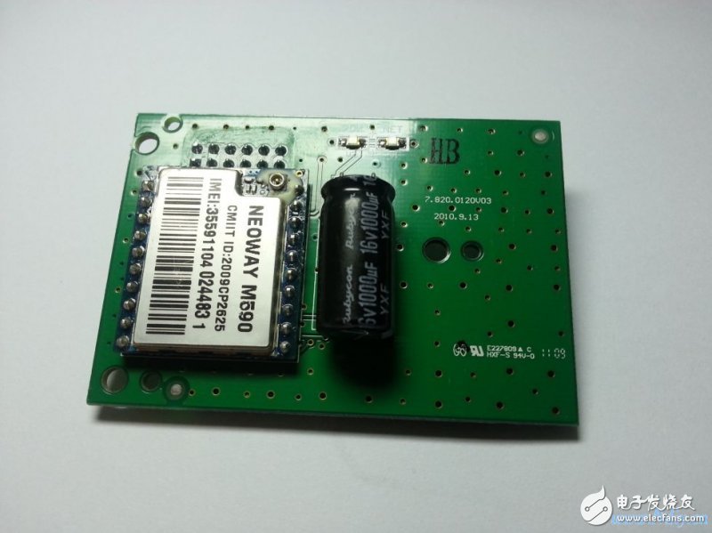
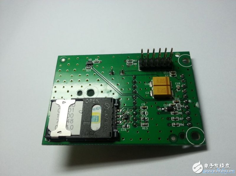
The first step: prepare GSM module, single chip microcomputer, peripheral circuit components, etc., as shown below, this is the GSM module used in DIY.
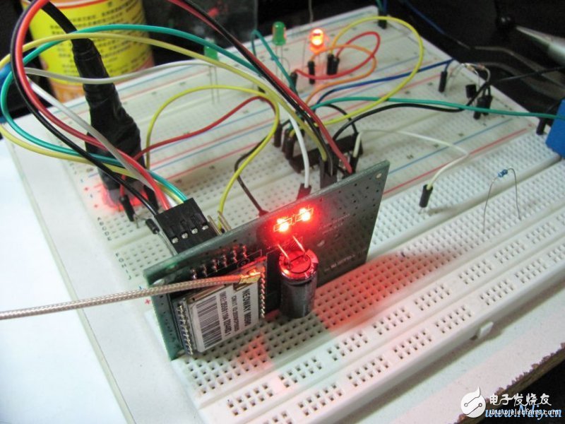
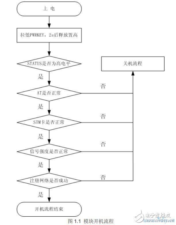
Step 2: Prepare the GSM module. Next, of course, you need to understand the GSM workflow and data transmission format. Among them, we need to briefly understand the commonly used AT commands, which are listed below, as shown below. Use breadboard to build temporary test and programming environment, provide prototype and reference for hardware and software design, Figure 1.1 shows the GSM module recommended boot code design flow;
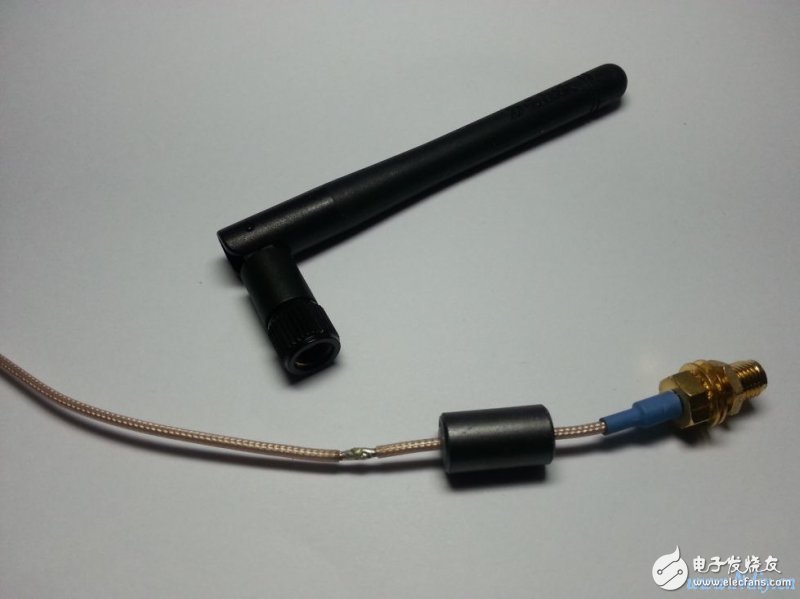
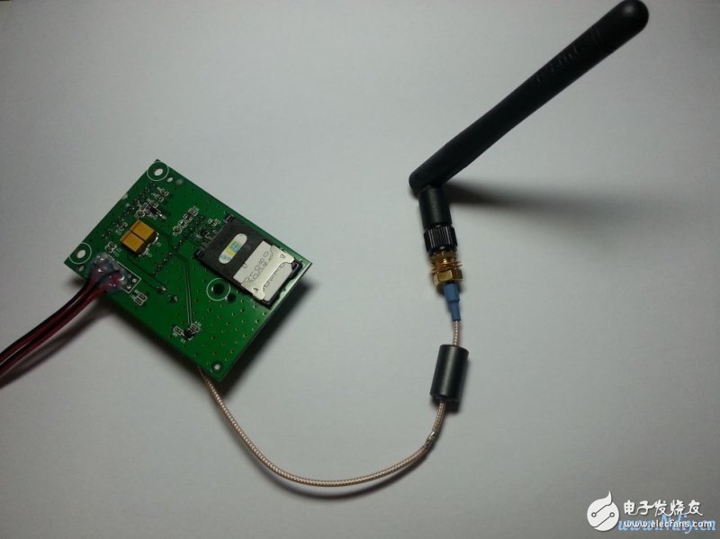
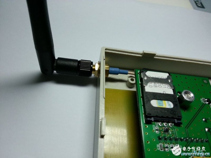
The third step: the software writing and debugging platform built by the breadboard, I wrote a stable and reliable program code, below we start to deal with the hardware, because the final application scenario is in the relatively small, more plumbing bathroom, GSM The signal will be affected, so I need to first enhance the antenna performance of the GSM module, and replace the PCB antenna that comes with the original module with the whip antenna used on the wireless AP. It turns out that the signal enhancement effect is obvious and no longer need to be afraid. There is no GSM signal in the bathroom~ as shown below, it is the whip antenna used in the transformation and the effect on the module.
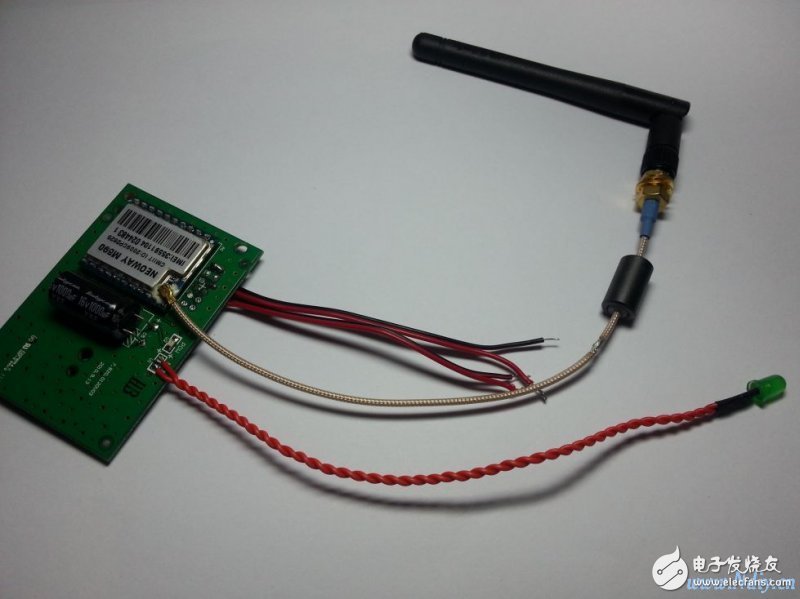
Step 4: Since the original module is welded with double-row pins, in order to facilitate the modification and installation, I need to replace the original pins with the wires and reinforce them with hot-melt glue. In this step, I also The LED indicator of the GSM network status is led out by a lead, and replaced with a green LED. When the outer casing is processed, the indicator light is installed on the outer casing to conveniently view the GSM network and the operating state of the module;
The fifth step: the program is written, the GSM module is processed, and then, naturally, the highlight of this DIY is - making PCB board
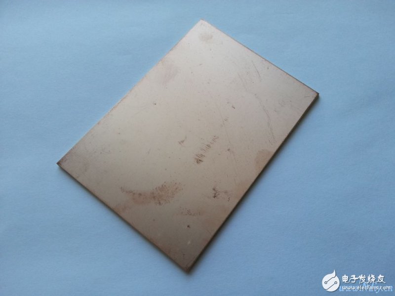
5.1 Preparing CCL
5.2 Drawing PCB diagram
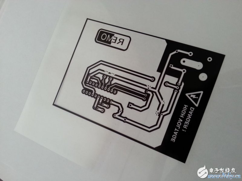
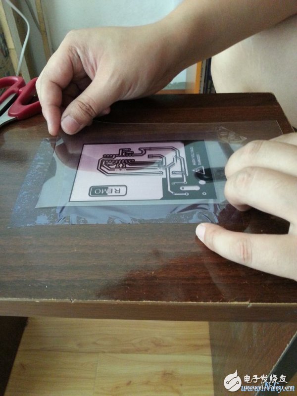
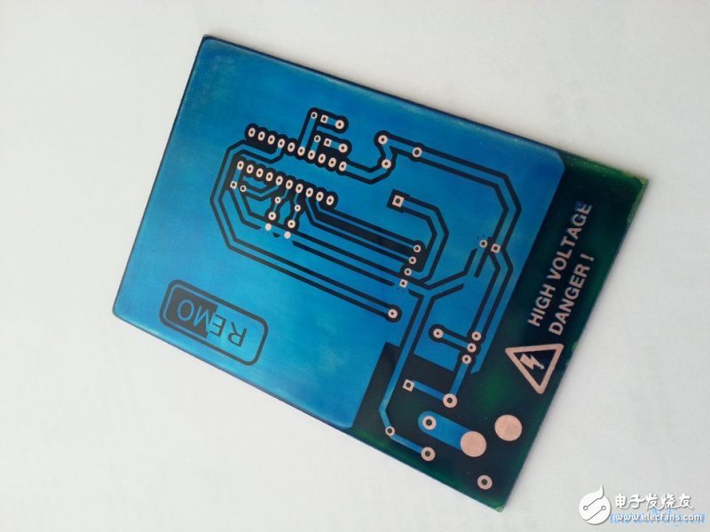
5.3 film, exposure
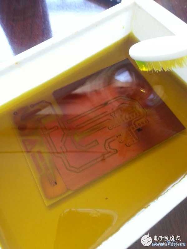
5.4 etching
5.5 Close-up of the upcoming PCB
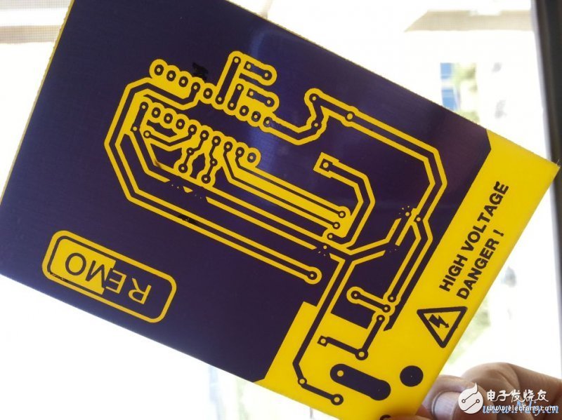
5.6 Blue oil
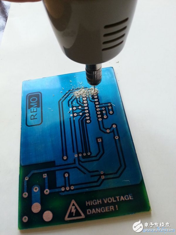
5.7 Punch, PCB completed
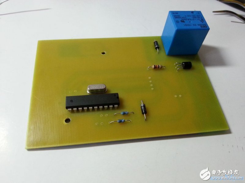
Step 6: Welding & Assembly
6.1 Soldering MCU and peripheral components
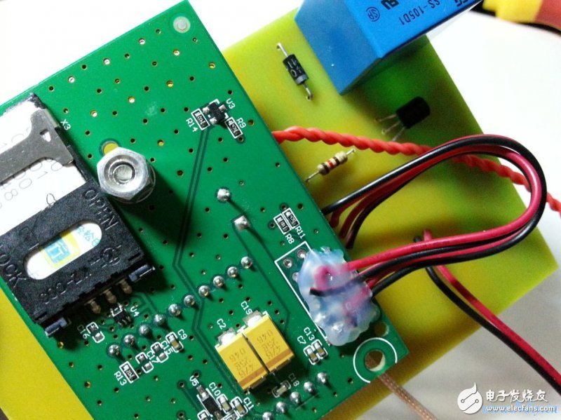
6.2 Installing the GSM Module on the PCB to complete the overall PCB design
Step 7: Assembly of the whole machine
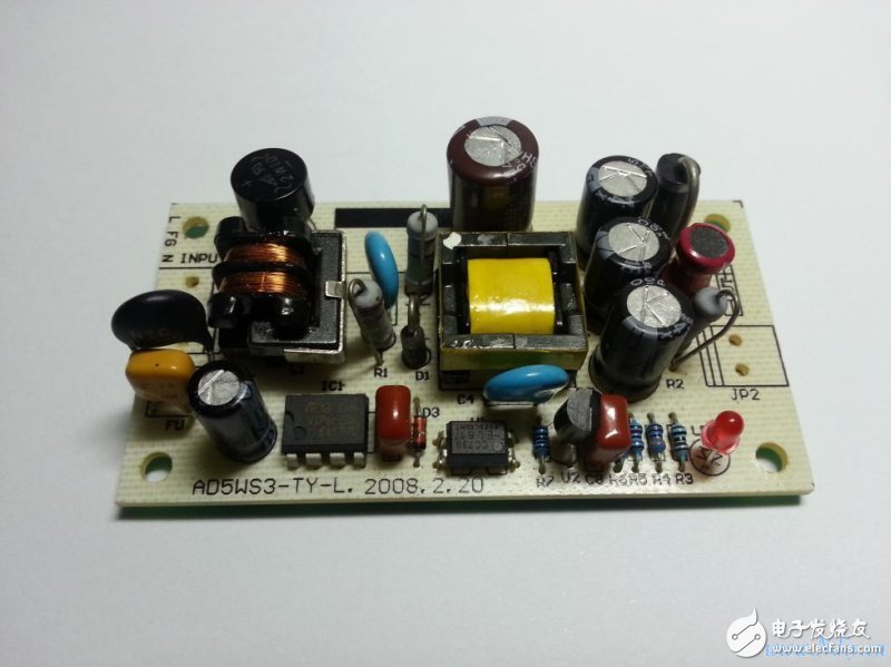
7.1 Preparing the Power Module
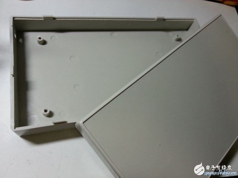
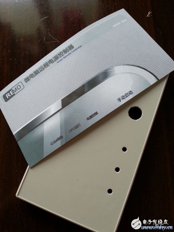
7.2 Preparing the plastic case
7.3 Install the whip antenna and install the PCB board
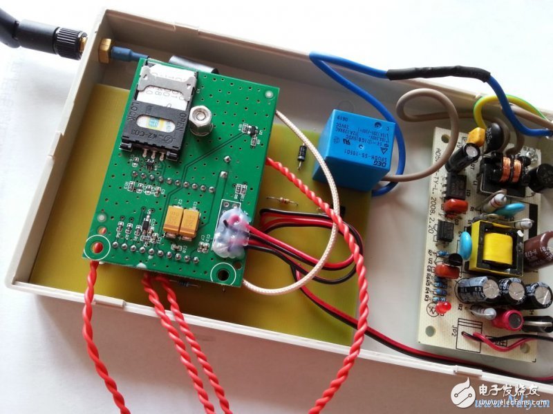
The following figure shows the effect of semi-finished products after installing power modules and PCBs into the casing.
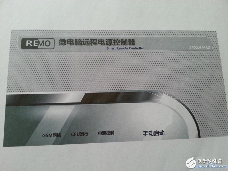
Step 8: With an electrical part that works, a beautiful case is of course essential. In this step, use PhotoShop to design a panel suitable for this DIY work, and punch holes in the appropriate position of the case to install. LED indicator and manual switch
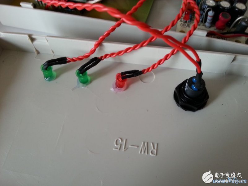
Step 9: Install the LED indicators on the front panel, manual buttons, etc., and finally install the housing
Now that the whole machine is assembled, here are a few of the smart remote power controllers.
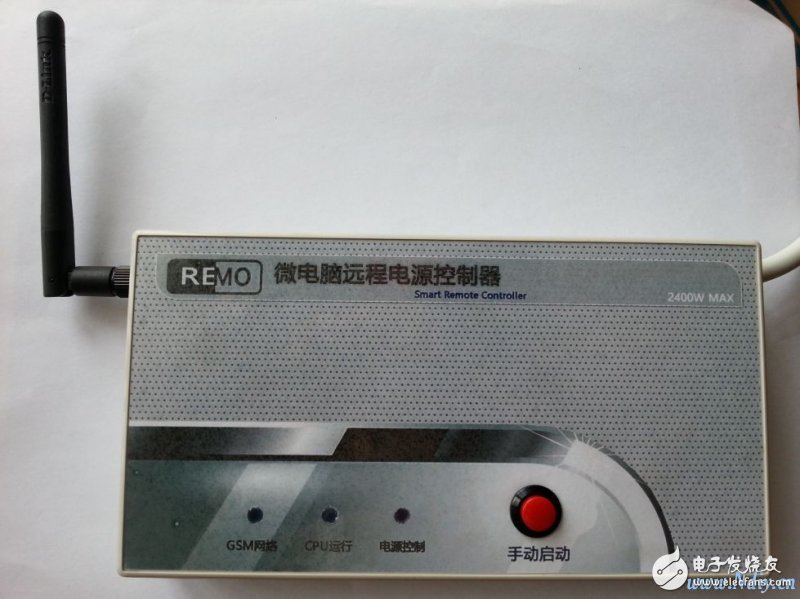
The following is the effect of the whole machine after installation in the bathroom, it looks pretty good~~
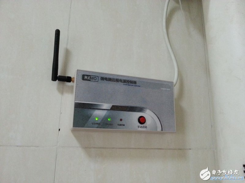
At this point, this smart remote power controller is complete, using this smart remote power controller to access the controlled appliances, I can control the power of the target appliance anytime, anywhere.
iPhone 6S Plus Battery Pack, OEM Li-ion Polymer 3.8v 2750mAh with 1 year warranty. We are offered iPhone battery replacement is made from our own cell and customerized protection board,FPC and connectioner. Which is durable and safety,still keep 90% capacity more than 400 cycle times. iPhone Repair Battery daily production 100-150,000pcs,defective rate as 3‰.
iPhone 6S Plus Battery Pack
Nominal voltage: 3.8V
Limited charge voltage: 4.35V
Capacity:2750mAh (10.45whr)
Cell size: 29x49x119mm
iPhone 6S Plus Battery Pack,iPhone 6S Plus Battery Pack Replacement,Battery Pack For iPhone 6S Plus,iPhone 6S Plus Lithium-Ion Battery
Shenzhen Aokal Technology Co., Ltd. , https://www.aokal.com