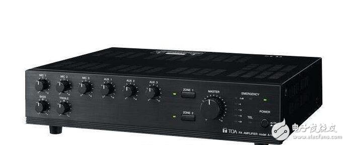
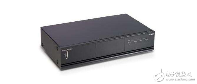
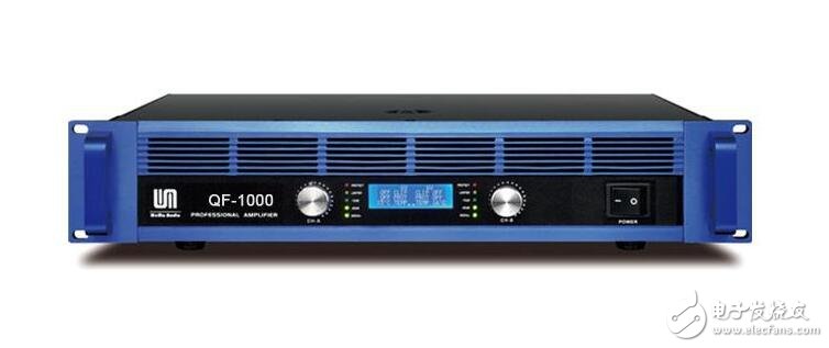
The power amplifier is called the power amplifier. It can be said that it is the largest family of all kinds of audio equipment. Its function is mainly to amplify the weak signal input by the sound source equipment, and generate enough current to push the speaker to reproduce the sound. Due to power, impedance, distortion, dynamics, and different ranges of use and control adjustments, different power amplifiers have different internal signal processing, circuit design, and manufacturing processes.

Power amplifier performance indicators:
Regardless of the AV amplifier and Hi-Fi power amplifier, the power amplifier is very strict, and there are clear requirements in terms of output power, frequency response, distortion, signal-to-noise ratio, output impedance, and damping coefficient.
(1) Output power
Output power refers to the power delivered by the power amplifier circuit to the load. At present, people's measurement methods and evaluation methods for output power are not uniform, and attention should be paid when using them.
1. Rated power (RMS)
It refers to the maximum power (strictly speaking, sine wave signal) that can be output by the power amplifier for a long period of time in a certain harmonic range. The average power when the harmonic distortion is often 1% is called the rated output power or the maximum useful power, the continuous power, the undistorted power, and the like. It is obvious that the nominal power values ​​will be different when the specified distortion preconditions are different.
2, the maximum output power
When the distortion size is not considered, the output power of the power amplifier circuit can be much higher than the rated power, and can output a larger value of power. The maximum power that can be output is called the maximum output power, and the aforementioned rated power and maximum output power are two. Output power with different preconditions
3, music output power (MPO)
The music output power MPO is the abbreviation of English Music Power Outpur, which refers to the output power of the power amplifier circuit when it works on the music signal, that is, the instantaneous maximum output power of the power amplifier to the music signal under the condition that the output distortion does not exceed the specified value.
The music output power can be used to evaluate the dynamic listening effect of the power amplifier. For example, a strong impact instrument sound suddenly appears behind a smooth music process. Some power amplifier circuits can provide a large output power in an instant to give a sense of strength. The power is not endless; some of the power amplifiers seem to be powerless. The ability to reflect this instantaneous burst of output power can be measured in terms of music output power.
4, peak music output power (PMPO)
It is the maximum music output power, and is another dynamic indicator of the power amplifier circuit. If the distortion is not considered, the maximum music power that can be output by the power amplifier circuit is the peak music output power.
Generally, the peak music output power is greater than the music output power, the music output power is greater than the maximum output power, and the maximum output power is greater than the rated output power. According to practice statistics, the peak music output power is 5-8 times of the rated output power.
(two), frequency response
The frequency response reflects the power amplifier's ability to amplify the frequency components of the audio signal. The frequency response range of the power amplifier should not be lower than the human ear's auditory frequency range. Therefore, in the ideal case, the main channel audio power amplifier has an operating frequency range of 20 -20kHz. Internationally, the frequency range of a typical audio power amplifier is 40-16 kHz ± 1.5 dB.
(three), distortion
Distortion is a phenomenon in which the waveform of the reproduced audio signal changes. There are many reasons and types of waveform distortion, including harmonic distortion, intermodulation distortion, and transient distortion.
(four), dynamic range
The ratio of the amplified minimum signal to the maximum signal level without distortion of the amplifier is the dynamic range of the amplifier. In practical use, the ratio uses dB to indicate the level difference between the two signals. The dynamic range of the high-fidelity amplifier should be greater than 90 dB.
The various noises in nature form the surrounding background noise, and the surrounding background noise and the sound intensity appearing in the performance vary greatly. Under normal circumstances, this intensity difference is called the dynamic range, and the excellent sound system should not input a strong signal. Overload distortion is generated, and when the weak signal is input, it should not be overwhelmed by the noise generated by itself. For this reason, a good sound system should have a large dynamic range, and the noise can only be minimized, but it is impossible to generate no noise.
(5), signal to noise ratio
The signal-to-noise ratio refers to the ratio of the size of the sound signal to the size of the noise signal. The number of decibels of the ratio of the output signal level of the attack and discharge circuit to the various noise levels of the output is called the signal-to-noise ratio.

(6) Output impedance and damping coefficient
1, the output impedance
The equivalent internal impedance exhibited by the amplifier output and the load (speaker) is called the output impedance of the amplifier.
2, damping coefficient
The damping coefficient refers to the ability of the power amplifier circuit to perform a resistance to the load.

The terminology of the power amplifier:
The scope of work
The working range refers to the operating frequency bandwidth of the power amplifier under the specified distortion and rated output power, that is, the range between the lowest operating frequency of the power amplifier and the highest operating frequency, in Hz (hertz). The actual operating frequency range of the amplifier may be greater than the defined operating frequency range.
Operating mode
The working modes of the power amplifier mainly include the following:
Time Division Duplex (TDD) mode:
In a TDD mode mobile communication system, different time slots on the same frequency channel (i.e., carrier) are received and transmitted, and the reception and transmission channels are separated by the guaranteed time.
The TDD system has the following characteristics:
(1) It does not require paired frequencies, can use various frequency resources, and is suitable for asymmetric uplink and downlink data transmission rates, and is particularly suitable for IP type data services;
(2) The uplink and downlink work at the same frequency, and the symmetrical characteristics of the wave propagation make it easy to use new technologies such as smart antennas to achieve the purpose of improving performance and reducing costs;
Time Division Multiple Access (TDMA) mode:
TDMA is the abbreviation of TIme Division MulTIple Access. The carrier of the same frequency is divided into several equal small time periods in a certain time, and the users of multiple different numbers use different small time periods to implement the connected communication mode. In short, it is a digital wireless technology that divides a narrow wireless channel into frame-like time segments (especially 3 and 8) and assigns each time segment to each user.
Transmission gain
Refers to the ratio of the output power of the amplifier to the input power, expressed in units of “dB†(decibel). The output gain of the power amplifier increases or decreases as the frequency of the input signal changes. This indicator is the most important basis for assessing the quality of power amplifiers. The smaller the decibel value, the flatter the frequency response curve of the power amplifier, the smaller the distortion, and the stronger the degree of reproduction and reproducibility of the signal.
Output Power
The power amplifier's power specification is strictly divided into nominal output power and maximum instantaneous output power. The former is the rated output power, which can be interpreted as the maximum value of the output power when the harmonic distortion changes within the standard range and can work safely for a long time; the latter refers to the "peak" output power of the power amplifier, which is interpreted as the power amplifier accepts When the electrical signal is input, the maximum output power that can be withstand instantaneously under the premise of ensuring that the signal is not damaged.
Receive gain
Gain is one of the main indicators of the antenna. It is the product of the direction coefficient and the efficiency, and is the performance of the antenna radiating or receiving the wave. The choice of gain size depends on the requirements of the system design for the coverage area of ​​the radio wave. Simply put, under the same conditions, the higher the gain, the farther the distance the radio wave travels. The larger the receiving gain value of the power amplifier, the stronger the receiving performance.
Lightning protection
Common direct lightning protection measures:
1 Lightning rod: Lightning rod is used to protect industrial and civil high-rise buildings and power distribution units of power plants, transformer stations, and individual sections of transmission lines. During the process of extending the lightning pilot circuit to the ground, due to the influence of the lightning rod distortion circuit, Gradually turn and hit the lightning rod, thus avoiding the possibility of lightning leading to the protected equipment and destroying the protected equipment and buildings. It can be seen that the lightning rod is actually a lightning rod, which leads lightning to itself, thereby protecting other equipment from lightning strikes.
2 Lightning line: The lightning protection line is also called the overhead ground line. It is a metal wire that is placed along the line at the top of the tower and has good grounding. The lightning protection line is the main lightning protection measure for the transmission line.
3 Lightning protection belts and lightning protection nets: Metal grids placed on the building along the corners, ridges, corners and eaves that are vulnerable to lightning strikes are mainly used to protect tall civil buildings.
Surge protection
Surge is also called a surge, as the name suggests is a transient overvoltage that exceeds the normal operating voltage. In essence, a surge is a violent pulse that occurs in just a few millionths of a second. Possible causes of surges are: heavy equipment, short circuits, power switching, or large engines. Products containing surge arresters can effectively absorb sudden bursts of energy to protect connected equipment from damage.
Surge protector, also known as signal lightning protection device, is an electronic device that provides security protection for various electronic devices, instruments, and communication lines. When a sudden current or voltage is suddenly generated in an electrical circuit or a communication line due to external interference, the surge protector can conduct the shunt in a very short time, thereby avoiding damage to other equipment in the circuit by the surge.

Power amplifier applications:
Whether in the global mobile communication system, third-generation mobile communication systems, wireless LAN and other civilian fields, or in the military fields such as radar, electronic warfare, navigation, etc., RF power amplifiers are the front-end devices in these systems, which are low-cost, high-efficiency, The requirement for small size increases rapidly.
As we all know, the power amplifier is the largest power loss in many modules of the RF circuit. As the core and front-end part of the system, its efficiency will directly affect the system efficiency. Therefore, the efficiency problem has become a research hotspot of modern power amplifiers. In most power amplifiers, the main loss of power is the transistor loss, which is mainly caused by voltage and current. Therefore, switching-type power amplifiers are proposed, mainly including Class D, Class E and Class F. Class F power amplifiers are specifically designed with a harmonic network to implement drain voltage and current waveform control. In theory, Class F power amplifiers have a drain efficiency of 100% and are called next-generation power amplifiers.
Conventional power amplifiers operate at low efficiency due to power consumption on the output circuit. To increase the efficiency of conventional power amplifiers, an ideal Class F power amplifier uses an output filter to control the harmonic content of the transistor's output voltage or current, normalizing the voltage and current waveforms of the transistor's output. Therefore, the angle parameter of the collector current is 90°, that is, the collector waveform is half a sine wave, the collector voltage waveform is a square wave, and the phase difference between the two is λ/4, so the waveform of the collector voltage and current There is no overlap zone to achieve 100% ideal efficiency.
gree , https://www.greegroups.com
![<?echo $_SERVER['SERVER_NAME'];?>](/template/twentyseventeen/skin/images/header.jpg)