![<?echo $_SERVER['SERVER_NAME'];?>](/template/twentyseventeen/skin/images/header.jpg)
Another explanation for EDA in the communications industry (telecommunications) is the enterprise data architecture. EDA gives an overall view of the enterprise-level data architecture and divides the framework and hierarchy according to the characteristics of the telecom enterprise. EDA is an acronym for Electronic Design Automation (Automatic Design AutomaTIon), developed in the mid-1960s from the concepts of Computer Aided Design (CAD), Computer Aided Manufacturing (CAM), Computer Aided Testing (CAT), and Computer Aided Engineering (CAE). Come here. With EDA tools, electronic designers can design electronic systems from concepts, algorithms, protocols, etc. A lot of work can be done by computer, and the whole process of electronic products from circuit design and performance analysis to designing IC layout or PCB layout. The automatic processing on the computer is completed. The concept or scope of EDA is now widely used. In the fields of machinery, electronics, communications, aerospace, chemical, minerals, biology, medicine, military, etc., there are applications of EDA. At present, EDA technology has been widely used in major companies, enterprises and institutions and research and teaching departments. For example, in aircraft manufacturing processes, EDA technology may be involved from design, performance testing and characterization to flight simulation.
The main functions of the electronic password lock include:(1) Digital input: Press a number key, the corresponding number is displayed on the rightmost digital tube, and all the previously entered numbers are shifted to the left by one. The design password is 4 digits, and the system can only display the first 4 digits of the input.
(2) Digital clear: When the clear key is pressed, all the values ​​entered previously are cleared and displayed as “----â€.
(3) Password release: Press the 55# button to release the old password of the electronic password lock.
(4) Password change: After the old password is released, the password can be changed. Enter any four-digit password number and press # to use the entered digit as the new password.
(5) Password lock: After entering the new password, press the 11# button to perform the password lock operation.
(6) Password unlock: press the 99# button, then enter the number; if the input is consistent with the system storage password, the password lock can be turned on; otherwise, it cannot be unlocked.
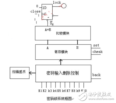
The structure principle of electronic password lockThe overall structure of the electronic code lock is shown in Figure 1. It includes a password lock input module, a control module and a display module.
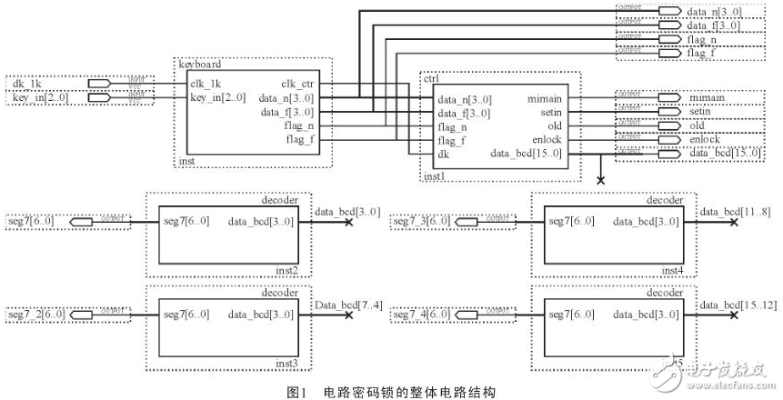
Design an electronic password lock, enter the password in the locked state, the password is 4 digits, use the data switch K1ï¾K10 to represent the numbers 1, 2, ..., 9, 0 respectively, the input password is displayed by the digital tube, and the last input The password is displayed on the rightmost digital tube, that is, each time you enter a single digit, the password is shifted to the left by one digit on the digital tube. The entered number can be deleted, and the last entered number is deleted. Each time one bit is deleted, the password is shifted to the right by one digit in the display of the digital tube, and "0" is added to the left empty bit. The state of one output level represents the open and close state of the lock. To ensure that the password lock owner can open the password lock, set a universal password and use it when the owner forgets the password.
Design tips:
Password input deletion control module
Hosting module
Comparison module
Scan display module
The system is mainly composed of two parts: the infrared transmitting module and the local processing receiving module. The overall design block diagram of the system is shown in Figure 1. The cores of the transmitting module and the local processing receiving module use AT89C2051 ($0.5940) and AT89S52 ($0.8482) microcontrollers respectively. The infrared signal is sent and received through the serial port for communication, and the two parts of the serial port working mode and the communication baud rate setting are the same.
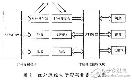
The AT89C2051 microcontroller is a streamlined version of the AT89C51 ($3.7500) with only 20 pins and a small footprint; it has a wide voltage operating range of 2.7 to 6 V; it has a low-power idle and power-down mode. The single chip microcomputer satisfies the requirements of low voltage power supply, low power consumption and convenient carrying of the system. In the local processing receiving module, the AT89S52 single-chip microcomputer is used, and the single-chip microcomputer has three timers. When the password and button* are set, the function of automatically resetting the button interval over 3s is designed, which is realized by timer T0 and T1 timing respectively; timer T2 sets the serial communication baud rate.
Design of infrared emission moduleThe infrared transmitting module is only a handheld remote control, which is composed of AT89C2051 single-chip microcomputer and keyboard circuit, button K and infrared light-emitting diode. The schematic diagram of the transmitting circuit is shown in Figure 2.
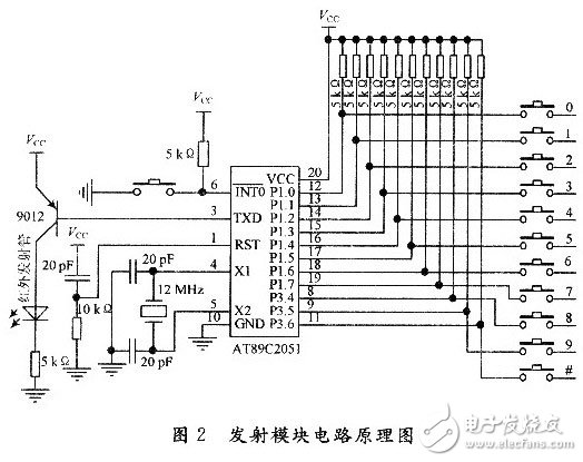
The password set by the transmitter module must be the same as the local receiver module (see section 2.2.1 for setting the password method). The password set is stored in the 31H to 38H unit of the RAM memory. In the standby state, the system works in the idle mode. When the button K is pressed, the system is powered on, and the password signal is sent in sequence. The advantage of this is that the password can not only be arbitrarily changed by the host, but also can be completed by pressing only one button when the remote control is*, which is convenient for the user.
The design of the receiver processing circuitThe control core of the local processing receiver circuit is the AT89S52 microcontroller. External keyboard circuit, infrared receiving circuit, * circuit, alarm circuit and button indicating circuit, etc., the circuit schematic is shown in Figure 3.
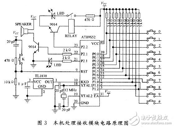
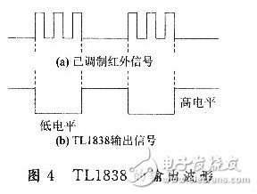
The infrared receiving circuit uses an integrated infrared receiving head TLl838 to receive the infrared signal. TLl838 integrates infrared receiving and amplifying, and can complete all the work from infrared receiving output to TTL level without any external components, and the size is the same as that of ordinary plastic triode. The output waveform of the TL1838 is shown in Figure 4. When receiving the infrared signal in the frequency band, TLl838 will output a low level, otherwise the data is high level, thereby demodulating the "intermittent" infrared signal into the original continuous square wave signal.
The alarm circuit uses a buzzer to sound the analog alarm. The buzzer is connected to the pin P2.1 of the CPU. The current is amplified by the NPN type triode, and the frequency and buzzer time of the buzzer are controlled by the single chip microcomputer. When the wrong password is input*, the high level is output from the P2.1 port so that the NPN type transistor 9014 is turned on, the buzzer is energized at both ends, and the buzzer emits an alarm sound of 3 s, when the password appears three times in succession. When the error occurs, the system will alarm for a long time, which effectively acts as an anti-theft.
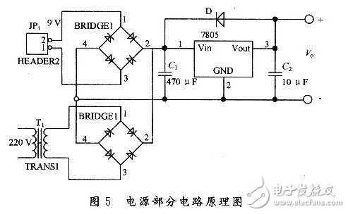
Power circuit designThe power supply part is regulated by the LM7805 ($0.2053) chip to provide a voltage of 5 V to the microcontroller. The circuit is shown in Figure 5. Mainly used for household AC, while using 9 V battery as backup power. The advantage of this is that even if the power is turned off, it will not be able to*.
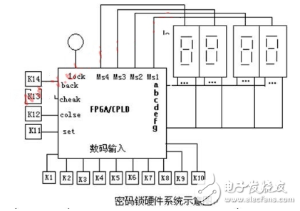
Because the AT89S52 MCU has 4 parallel input and output ports, the hardware resources are sufficient, the keyboard circuit uses a relatively simple independent button; the circuit uses a relay to control a green LED instead of a specific lock. When the password is correct, *5 s And then automatically lock; P2. The O port is connected to a red LED, and its light is turned on and off to remind the user whether the button is pressed. This subtly reminds the user that the password is effectively protected.
BNC Connector, DC Connector, Coaxial Cable Connector,Coax Connector,DC Power Connector
Chinasky Electronics Co., Ltd. , https://www.cctv-products.com