![<?echo $_SERVER['SERVER_NAME'];?>](/template/twentyseventeen/skin/images/header.jpg)
ECG signal is one of the earliest bioelectrical signals that humans have studied and applied in medicine and clinic. It is easier to detect than other bioelectric signals and has more intuitive regularity. Due to the sudden and long-term nature of heart disease, heart disease patients often need long-term treatment and monitoring, so it is of great clinical value to have long-term ECG records. Long-term ECG records can record transient abnormal ECG activities that are difficult for patients to detect during normal ECG detection, providing an important basis for disease analysis. When the ECG monitor was first applied in the 1960s, it could only monitor ECG signals, called a single-parameter monitor. With the advent of large-scale integrated circuits and microprocessors, current ECG monitors have been able to monitor dozens of parameters. In view of the difficulty in identifying ECG signals and the professionalism of ECG-related operations, the implementation of ECG monitoring is often limited to hospitals and health institutions, and daily ECG monitoring is not easy to implement.
The wearable medical instrument has basic functional modules such as physiological signal detection and processing, signal feature extraction and data transmission, which can realize non-invasive continuous monitoring, diagnosis and treatment of the human body. In the traditional ECG monitor, the hardware devices are mainly connected by communication cables, and the operation platform is also based on wired devices. Although there are certain applicability in certain occasions such as hospitals and communities, but there is no existing The integration of personal communication terminals (such as mobile phones, PDAs, portable computers, etc.). In view of this situation, this study designed and implemented a more convenient and comfortable wearable wireless ECG recorder under the premise of ensuring the quality of signal acquisition, using low-power ECG acquisition chip ADS1191 and low-power single-chip microcomputer. The MSP430F2112 constitutes a signal acquisition circuit. The collected ECG signals can be transmitted to the communication terminal for display and analysis through Bluetooth. The wireless transmission and wireless charging technology are used to completely seal the entire device, achieving waterproof function and meeting medical safety standards.
1 system structure and designWearable wireless ECG recorders should have low power consumption, small size, and high processing speed. The size of the ECG electrode used in this study is about 30~75 mm. Considering the support capacity of ECG electrode stickers, the height of the equipment expected in this study is about 0.5 cm and the weight is < 30 g. Simulation results show that the ECG electrode holder can support the volume and weight of the device well and does not fall off during exercise.
The ECG recorder is mainly composed of an electrode patch connection module, an ECG front end, a main control unit, a Bluetooth module, a wireless charging module, a lithium battery, a voltage regulator, and a power management module. Block diagram, see Figure 1.
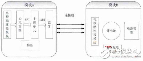
Figure 1 Block diagram of wearable wireless ECG recorder
The design of the surface ECG signal has the characteristics of weak amplitude and vulnerability to interference. The ECG signal collected by the module is preamplified by a differential amplifying circuit with high input impedance to suppress zero drift and reduce interference of common mode signals; after further amplification (about 1000 times), the interference signal is filtered out. Level boost; then sent to the core processing controller for processing. The module is implemented by TI's low-power ECG acquisition chip ADS1191. After the ECG signal is filtered, amplified, A/D converted, etc., it is sent to the low-power MCU MSP430F2112 for further analysis and processing. The wireless transmission is realized by the HM-6 Bluetooth module (manufactured by Huamao Technology Co., Ltd.) for pocket devices.
1.2 Power supply part (module B) designWireless charging technology is derived from wireless power transmission technology. The mainstream wireless charging technology in the market is mainly realized by three methods (electromagnetic induction, radio wave and resonance). The wireless charging module is implemented by Qi wireless charging technology and BQ24201 charger. Qi is the world's first standardization organization to promote wireless charging technology - the "wireless charging" standard introduced by the Wireless Charging Alliance (WPC), with two features of convenience and versatility. Qi wireless charging technology uses magnetic resonance to transfer charge in the air between the charger and the device. The coil and capacitor form a resonance between the charger and the device to achieve efficient transmission of electrical energy. The basic principle is to form between the two coils. Resonance to achieve wireless transmission of electrical energy. The BQ24201 is a lithium-ion battery or lithium polymer charger that integrates internal high-precision voltage regulation, power MOSFET, temperature monitoring, state of charge, and charge termination circuitry on a single chip; fewer external components, space and cost savings .
The power management module uses BQ24312 as the front-end protection scheme for the lithium-ion charger, which provides over-voltage protection of 4.25 V. The ADuM5000 is used for power isolation. The ADuM5000 is an isolated DC/DC converter based on ADI technology. The circuit provides 5 V power isolation. According to the product requirements, the ECG recorder needs to perform > 4 h of uninterrupted ECG signal acquisition and transmission. After estimating the overall circuit, the study intends to use a 90 mAH rechargeable lithium battery. Power supply part charging circuit diagram, see Figure 2. The lithium battery provides a stable 3.3 V digital voltage and analog voltage for the ADS1191, MSP430F2112, and Bluetooth modules via the MIC5205LB regulator chip.
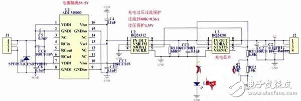
Figure 2 power supply part charging circuit diagram
The ECG software development environment uses the cross-compiler IAR Embedded Workbench designed by IAR for MSP430 microcontrollers, and the writing language is C language. System software flow chart, see Figure 3. In order to meet the low power consumption design requirements, this study uses the following methods to control power consumption in software design:
1 According to the function, the software is divided into several relatively independent modules, which are triggered by interrupts. 2 Use software to control the chip that is temporarily not working to enter the sleep or idle state. 3 Use the program with short machine cycle to optimize each module program and reduce the actual system. Run time to reduce system power consumption.
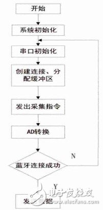
Figure 3 ECG recorder software flow chart
The physical map of the ECG recorder designed and implemented is shown in Figure 4. As can be seen from Fig. 4, the recorder is mainly divided into two parts, each having a diameter of about 30 mm and a thickness of about 5 mm. The overall length is about 10 cm and the weight is 25 g. The connecting lines between the two wires include the ground wire and the power cord; The electrode buckle is embedded and directly attached to the electrode sticker when in use. The position of the electrode sticker is about 3 cm below the midline of the left clavicle, as shown in Figure 5.
The ECG recorder ECG front-end ADS1191 and processor MSP430F2112 consume 0.98 mA while running, and the Bluetooth real-time data transmission power consumption is 16 mA. Figure 6 shows the ECG waveform of a male subject undergoing the test. It can be seen that the ECG waveform after de-noising, smoothing, etc. is stable, the baseline drift is not obvious, and the P, QRS, and T-wave characteristics are obvious. Can be used for arrhythmia analysis.

Figure 4 is a physical map of the ECG recorder, where (a) is the front view and (b) is the rear view.
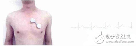
Figure 5 ECG recorder using schematic diagram left Figure 6 Receiver ECG waveform diagram right
(1) Input impedance. A “100 mV 10 Hz†sine wave is generated by the signal generator, and a 620 kΩ resistor is connected to the input of the ECG recorder. The measured signal generator sinusoidal signal amplitude U=98.8 mV, the voltage U at the input end of the recorder =95.84 mV, through calculation, the input impedance of the ECG recorder is R=20.07 MΩ. According to the National Electrocardiograph standardization document, the input impedance of the ECG machine must be ≥ 2.5 MΩ. Therefore, the input impedance of the ECG recorder meets industry standards.
(2) Frequency response. In the test circuit, the output frequency of the signal generator is continuously changed from 0.1 Hz to 150 Hz (that is, the so-called "sweep") and the amplitude is kept at 100 mV. At the output, the oscilloscope or other recorder will be used. The amplifier records the corresponding output level of this continuous change to obtain the frequency response curve of the device. After measuring in the frequency range of 0.1 ~ 150 Hz, the amplitude of the signal amplification of the ECG recorder is 2.37 dB, which is less than the 3 dB specified by the state, which meets the requirements.
(3) Common mode rejection ratio. The common mode rejection ratio refers to the ratio of the amplification factor at the time of differential mode input to the amplification factor at the time of common mode input, and reflects the anti-interference ability of the electrocardiograph. First measure the amplification factor of the common mode input, introduce the “1.5 V / 50 Hz†signal from the signal source, input it to the shorted input terminal, connect the signal source ground line to the right foot drive, record the output signal amplitude; then and the difference The signal amplification factor at the time of input is compared, and the calculated common mode rejection ratio is 106.4 dB, which is in line with the national electrocardiograph standard.
3 ConclusionThe portable ECG recorder designed and implemented in this study has low power consumption and small volume. It has the following features: 1 Easy operation, simple measurement, low cost, easy to promote; 2 Non-invasive, safe, accurate and repeatable measurement; The waveform can be displayed in real time; 4 has wireless charging function. The ECG recorder can be widely used for long-term real-time monitoring of ECG signals after industrialization.
Home Appliances Wire
We supply rigorous UL standard electronics wires used in internal wiring of home appliances and electrical equipment such as air conditioner, humidifier, washing machine, fridge, rice cooker, microwave etc. Insulations include PVC, SXL(XLPVC), silicone rubber and FEP with the heat resistance from 176°F(80°C) to 392°F (200°C). Feyvan electronics has carried R&D on covering materials for many years, even some special Insulation materials such as TPE, TPU, insects prevention and rats prevention, our engineers have much experience to provide professional solutions for you.
Home Appliances Wire,Electrical Panel Wiring,Home Wiring,Home Electrical Wiring
Feyvan Electronics Technology Co., Ltd. , https://www.fv-cable-assembly.com