![<?echo $_SERVER['SERVER_NAME'];?>](/template/twentyseventeen/skin/images/header.jpg)
With the rapid spread of sensing technology in automotive and consumer electronics, microelectromechanical systems (MEMS) have entered the mainstream in recent years. For control and signal conditioning, MEMS-based sensors necessarily require close coupled electronic circuitry. The electronic circuit is either independent of the MEMS or embedded in the MEMS in an analog/mixed signal integrated circuit in one die. MEMS design typically requires a team of experts who use 3D mechanical CAD and finite element tools for functional verification; IC design is implemented through EDA tools such as the Cadence Virtuoso customer design environment. Traditionally, MEMS designers have handcrafted Verilog-A models for placement into IC designs. These hand-made models are often too simple and non-parametric. In addition, creating these models is quite time consuming and requires expertise. As the market from the consumer electronics industry moves toward more features, lower cost and faster time to market, the shortcomings of traditional design methods are becoming increasingly apparent. This article describes a MEMS device design and a new approach to simulation with the integrated electronics in the Cadence Virtuoso design environment.
IntroductionMicroelectromechanical systems (MEMS) are micron or nanoscale devices that are typically fabricated in the form of integrated circuits (ICs) and benefit from miniaturization, integration, and batch processing of semiconductor fabrication. Unlike integrated circuits, which only include electrical components, MEMS devices incorporate technologies from multiple physical domains that may include electronic, mechanical, piezoelectric, magnetic, and/or optical components. A MEMS product, a component that can be purchased and assembled on a printed circuit board, is typically composed of a MEMS sensing or driving component (MEMS device) and corresponding integrated circuits (ICs) that process the input and output signals.
MEMS products are often designed with at least two groups of experts: MEMS designers and IC designers. MEMS designers are usually PhD-level experts who use their own 2D and 3D mechanical CAD tools to design inputs and simulate with Finite Element Analysis (FEA) tools. IC designers, a unique second group, rely on custom IC design and simulation environments such as Cadence Virtuoso. They create schematics of the electronics in the Virtuoso schematic editor and then simulate behavior in the Virtuoso Spectre or UltraSim circuit simulator.
Of course, given that MEMS and ICs must work together, IC designers need a behavioral model of MEMS and plug it into their schematic design. In this article, we first describe the traditional approach, and MEMS designers provide a MEMS behavioral model for their IC design peers. Then, we briefly introduce our new MEMS-IC collaborative design platform, MEMS+, and discuss the advantages of this structured approach over traditional approaches.
Traditional MEMS-IC design methodTo support MEMS devices and their ICs in simulations in Spectre or UltraSim simulators, MEMS designers typically use the Verilog - A hardware description language to manually plot behavioral models of MEMS devices. Handcrafted models may be based on analytical formulas, or look-up tables, or based on models derived from finite element analysis results. This traditional approach has many drawbacks. First, it takes time and requires professional knowledge. Since the method is manual, some steps are repeated each time the MEMS design changes. Second, hand-made models, in simple terms, do not fully capture the complex behavior of MEMS devices. For example, relative to the six degrees of freedom of the actual device—three translations (x, y, and z) and three rotations—these models are often limited to one mechanical degree of freedom. For example, for a multi-axis accelerometer model, only one direction of motion may be captured, while coupling with other directions may be unfavorable. Third, manual models cannot be parameterized in terms of machining processes or geometric variables. Excessive simplification and lack of parameterization limit IC designers to optimize their designs. Conversely, analog circuits may be designed to be conservative, resulting in higher energy consumption. In addition, the limitations of hand-made models make it difficult to verify the corners and investigate the effects of processing, all of which can affect the entire system.
Performance. Ideally, MEMS designers should be able to create and modify MEMS designs in a 3D solid design environment and then automatically generate the required Virtuoso simulation models and layouts. The simulation model should be parameterized, and the complex behavior of MEMS devices should be accurately obtained, while at the same time fully and effectively allowing MEMS and IC to co-simulate in a reasonable CPU time.
A new institutional approach to MEMS-IC verificationIn this paper, we present a new integrated approach to MEMS-IC design, simulation, and product development based on a single MEMS design representation. This new approach enables MEMS designers to work in a new 3D environment called MEMS+. MEMS+ adapts to the needs of the designer and easily derives behavioral models that are parametric and compatible with the design and simulation environment that IC designers need. At the same time, IC designers can add MEMS devices to a schematic, just like adding any other analog or digital components. Parameters of the MEMS behavioral model may include process variables such as changes in material properties and dimensions, as well as geometric properties of the design. It is expected that the complexity and accuracy of these models will enable both MEMS-IC performance and yield design optimization.
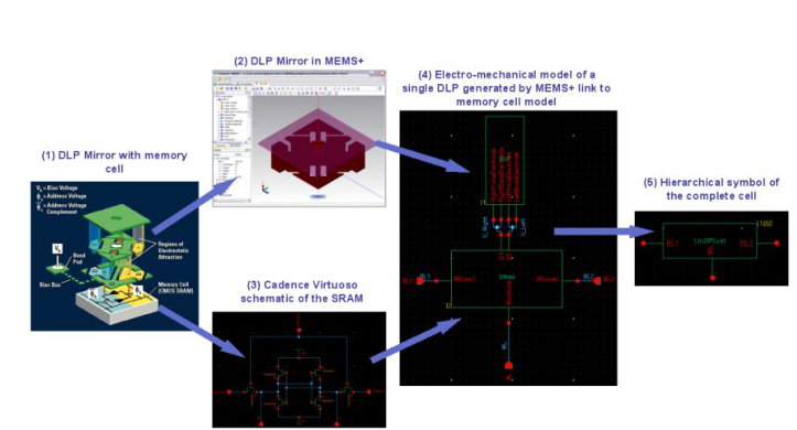
We describe a novel MEMS design flow that builds a reference model into a new 3D MEMS design platform, MEMS+. MEMS+ works with Cadence Virtuoso to provide a sample of a structured MEMS-IC design flow that facilitates the automated connection of MEMS designs and IC designs. MEMS+ also supports functional or algorithm level design through integration with MathWorks' MATLAB Simulink. The MEMS base component library has proven to be suitable for many types of MEMS devices. For example, simulations of accelerometers controlled by sigma-delta modulators have been shown in the references.
Ultrasonic Annunciator,Ultrasonic Piezo Annunciator,Outdoor Ultrasonic Annunciator,Ultrasonic Piezoelectric Annunciator
NINGBO SANCO ELECTRONICS CO., LTD. , https://www.sancobuzzer.com