![<?echo $_SERVER['SERVER_NAME'];?>](/template/twentyseventeen/skin/images/header.jpg)
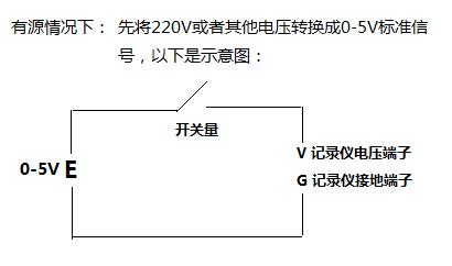
In the case of active:
The first method: using the transmitter, such as the active signal voltage of 220V, can be converted to 0-5V by voltage transmitter or other standard recorder can receive signals (0-10V, 4-20mA, etc.) ), the recorder configuration is set to 0-5V input, the range corresponds to 0-1, the switch can be connected to the loop in the circuit, and the corresponding terminal of the recorder can be connected. That is, when the switch is off, the recorder displays 0, then 0 means disconnected, when the recorder shows 1, 1 means closed.
The second method: using a relay. Connect the switch signal to be recorded on the site to the relay, and connect the 220V power supply into the circuit in series. Since the relay outputs a switching signal, this is equivalent to turning the active into passive and passive. There are three ways to record. Not directly through the alarm output.
In the passive case:
The third method: if the switching quantity is without voltage, then it can be used as the power supply with the 0-5V or 0-10V switching power supply as in the first method, and the switching signal is serially connected to the loop, and The corresponding terminal connection of the recorder is OK. The meter configuration is set to the corresponding signal input, such as 0-5V, the range is set to 0-1V, then 0 means disconnected, 1 means closed.
The fourth method: using thermocouple signal input, such as the instrument is set to K-type thermocouple signal, the range is set to 0-1, the principle is to connect the recorder and the switch amount in series, the configuration recorder is set to break the line to the starting point Then, when the switch is disconnected, the recorder displays 0, indicating the disconnected state; if it is closed, the wiring will short the voltage and ground. This time indicates the cold junction temperature, because the cold junction temperature If the maximum range set by the recorder is exceeded, the recorder will display 1, indicating that the switch is closed.
The fifth method: using the thermal resistance signal input, a 250 ohm resistor in the loop is entered, the meter configuration is set to pt100, the range is set to 0-409 ° C, because the resistance of 409 ° C corresponding to pt100 is 250 ohm, instrument cluster In the state, the disconnection is set to the starting point. When the switch is disconnected, the recorder will display 0; if the recorder displays 409, then the loop is open, the loop resistance is 250 ohms, indicating that the switch is closed. status.
Laptops,windows Laptops,win11 Laptops,win10 Laptops
Jingjiang Gisen Technology Co.,Ltd , https://www.jsgisengroup.com