![<?echo $_SERVER['SERVER_NAME'];?>](/template/twentyseventeen/skin/images/header.jpg)
The brightness of the LED changes, we control the current of the LED by pulse width modulation (PWM); the pulse current waveform generated is the culprit of EMI. LED dimming requires PWM control, but the EMI it produces must also be suppressed.
Well, your new design is very bullish, it can almost meet EMI requirements, but not exactly. To your surprise, the circuit produces conducted EMI just beyond what you have to meet, and at least some of this EMI comes from dimmable LEDs.
The brightness of the LED changes, we control the current of the LED by pulse width modulation (PWM); the pulse current waveform generated is the culprit of EMI. LED dimming requires PWM control, but the EMI it produces must also be suppressed.
The schematic below shows a simple way to suppress EMI.
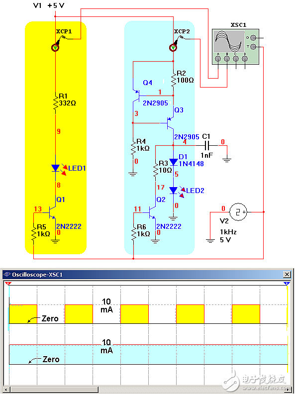
Figure 1: EMI suppression of PWM-controlled LEDs
The yellow and blue portions in the figure are LED dimming circuits before and after suppression, respectively. The yellow circuit on the left is easy to understand. The switch of transistor Q1 controls the on and off of the LED current. However, the current drawn from the +5V supply also changes up and down, and EMI is generated.
The blue part on the right is the improved circuit. It adds a constant current source consisting of Q3 and Q4. The current of the constant current source flows through the LED when Q2 is turned off, and does not flow through the LED when Q2 is turned on. Like the yellow circuit on the left, the duty cycle of the pulse current on the LED controls the LED brightness, but the current drawn from the +5V supply remains nearly constant, so there is little EMI.
Indeed, one difference between the two circuits is the opposite phase. The driver on the right uses a lot more components than the one on the left, and it consumes more power than the left. However, if you can afford these costs, the benefits of EMI reduction may also be worthwhile.

AC wall 5V 2A power adapter with multiple tips works for many small 5V electronics. Like Scanner, Router, Bluetooth speaker, Foscam Wireless IP Camera, CCTV camera, USB hub, bluetooth GPS Receiver, tv box, tablets, Baby Monitor, Graco Swing, Home Phone System, VoIP Telephone Routers, Serato DJ Controller, DVR, ADSL Cat, External battery, hubs, switches, Led Strip, String Lights, vibrator, Raspberry pi 3 Raspberry Pi A/A+/B/B+ Raspberry Pi Zero and more 5V devices. (5V ONLY)
Worldwide Input: 110-240V; Output: 5V 1000mA, 1.5A, 1.75A, 5V 1A, 5V 500mA, 5V 2.1A, Max 10W. DC Tip Polarity: Central Positive(+). Please read manual carefully before using 5vdc power supply.
Design-safeguard features against incorrect voltage, short circuit, internal overheating and overloading. This 5v Ac power supply charger is made from quality material to ensure the long lifetime. Power your 5v electronics perfectly and replaces lots of 5 volt power chargers
Package include: 1 x High Quality 5V 2A AC DC Power Adapter, 1 Set x Tips
5V Switching wall charger 6V Switching wall charger 9V Switching wall charger 12V Switching wall charger 15V Switching wall charger 19V Switching wall charger 24V Switching wall charger 36V Switching wall charger 48V Switching wall charger
Shenzhen Waweis Technology Co., Ltd. , https://www.huaweishiadapter.com