![<?echo $_SERVER['SERVER_NAME'];?>](/template/twentyseventeen/skin/images/header.jpg)
Today, I will introduce a national invention authorized patent-a MEMS thermal mass gas meter equipped with a multi-pass measuring device. The patent was applied for by Liaoning Sky Technology Co., Ltd., and the authorization was announced on March 29, 2017.
Content descriptionThe utility model relates to a gas meter, in particular to a MEMS thermal mass gas meter equipped with a multi-pass measuring device.
Background of the inventionAt this stage, medium and low pressure civil and commercial gas users mainly use diaphragm gas meters, waist wheel flow meters, turbine flow meters, etc. These meters have mechanical moving parts inside, which require regular maintenance, high maintenance costs, and long-term use. The accuracy is not easy to guarantee; the measurement range is narrow and the range ratio is small, especially for the measurement of small flow rates, which is prone to leakage; the meter has a large product and weight and is inconvenient to install. When the flow meter is installed in the pipeline, the front straight pipe section is required to be 5 to 10 times or larger than the diameter of the flow meter. This requires a long front straight pipe section for a larger diameter meter, which cannot meet the requirements due to installation restrictions in some places.
The patent document with the publication date of March 30, 2011 and the publication number CN101126652B discloses an electronic mass flow gas meter, which includes a gas meter housing with a specific air-tight cavity, and a gas pipe in the housing It is an independent air inlet pipe, as well as the flow detection tube and the air outlet pipe connected together. The air inlet and air outlet pipes are respectively connected to the inlet and outlet of the shell. The downstream end of the flow detection tube is connected to the air outlet and suspended horizontally in the shell. The flow detection tube has a mainstream airway and a bypass airway. A device for shunting is provided in the mainstream airway between the two through holes that communicate with the bypass airway. The cross-sectional area of ​​the bypass airway is smaller than that of the mainstream airway. Cross-sectional area, the signal sensor module of a thermal mass flow sensor is set on the inner wall of the bypass airway for detection. The main function is that the signal sensor module measures the less flow in the bypass, passing through the mainstream airway and the bypass. The area ratio of the air passage expands the measurement range of the gas meter. It can measure the mass flow of the passing gas, and can prevent the dust contained in the gas from adhering to the original sensor. This gas meter can realize gas metering, but requires a long front straight pipe section. If there is a valve or elbow in the pipe section in front of the air inlet, a bias flow will be generated, so that the flow rate of the gas entering the bypass duct is proportional to the flow rate of the mainstream duct Changes will occur, affecting the accuracy of gas meter measurement.
Summary of the inventionThe problem to be solved by the utility model is to address the above shortcomings and provide a MEMS thermal mass gas meter equipped with a multi-pass measuring device that has simple structure, small size, light weight, easy maintenance, and does not require temperature and pressure compensation.
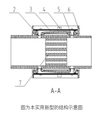
The technical solution adopted by the utility model to solve its technical problems is: a MEMS thermal mass gas meter equipped with a multi-pass measuring device, which includes a MEMS mass flow sensor and a bluff body, and is characterized in that it is located inside the mainstream airway 1 A bluff body 7 is installed, and the bluff body 7 is located between the bypass inlet 2 and the bypass outlet 5. The bypass inlet 2 is connected to the bypass outlet 5 via the bypass air passage 3, and a MEMS mass flow sensor 4 is installed above the bypass air passage 3, and the MEMS mass flow sensor 4 is fixed by a sensor base 6. Bypass inlet 2, bypass air passage 3, MEMS flow sensor 4, bypass outlet 5 constitute a bypass detection device, 1# bypass detection device 8, 2# bypass detection device 9, 3# bypass detection device 10 , 4# Bypass detection devices 11 are placed on the outside of the mainstream airway 1 in a symmetrical distribution.
The beneficial effect of the utility model is a MEMS thermal mass gas meter with multi-pass measurement. The MEMS flow sensor can measure the mass flow of gas without temperature and pressure compensation. The MEMS sensor is installed on the bypass, so that the anti-pollution ability is improved. In addition, the flow measurement range of the gas meter can be expanded by adjusting the split ratio of the measuring pipe and the bypass. The flow measurement method of multi-bypass sensors solves the change of the flow ratio between the mainstream airway and the bypass airway caused by the gas flow of a single bypass airway through the multi-point measurement of multiple bypass airways. The weighted average calculation of the data measured by the airway improves the measurement accuracy, repeatability and reliability of the measuring instrument, and reduces the length of the straight pipe section in front of the flow instrument.
The utility model has no mechanical moving parts, no mechanical wear, low failure rate and long service life. Covering medium and low pressure civil, commercial gas users and industrial users, the range ratio is up to 1000:1, and the ultra-wide range prevents the meter from leaking in small flow. It has small size, light weight, no noise, and no Affected by magnetic field, anti-disassembly, easy installation, good zero point stability, good repeatability, high accuracy, low starting flow, etc., multiple sensors work at the same time, which also improves the reliability of the measuring device.
Micro Coreless Motor product introduction:
Micro Coreless Motor in structure broke through the traditional motor rotor structure, USES is no rotor, also called the hollow rotor cup type.Hollow cup motor with brush and brushless divides into two kinds, brush with hollow cup motor rotor iron core, without brush hollow cup motor stator iron core.Winding adopts delta connection.

Function: fast speed, suitable for aircraft model, electric toothbrush,USB fan and other products.

Characteristic: the volume is 6MM 7MM fast.
Features: small size, fast speed, dc high speed motor starting voltage 0.6v is not possible for other motors.Wear shaking head, strong vibration feeling.

Operating temperature range:
Micro Coreless Motor should be used at a temperature of -10~60℃.
The figures stated in the catalog specifications are based on use at ordinary room temperature catalog specifications re based on use at ordinary room temperature (approximately20~25℃.
If a Micro Coreless Motor is used outside the prescribed temperature range,the grease on the gearhead area will become unable to function normally and the motor will become unable to start.Depending on the temperature conditions ,it may be possible to deal with them by changing the grease of the motor's parts.Please feel free to consult with us about this.
Storage temperature range:
Hollow cup motor should be stored ta a temperature of -15~65℃.
In case of storage outside this range,the grease on the gearhead area will become unable to function normally and the motor will become unable to start.
Service life:
The longevity of hollow cup motor is greatly affected by the load conditions , the mode of operation,the environment of use ,etc.Therefore,it is necessary to check the conditions under which the product will actually be used .The following conditions will have a negative effect on longevity.Please consult with us should any of them apply.â—Use with a load that exceeds the rated torque
â—Frequent starting
â—Momentary reversals of turning direction
â—Impact loads
â—Long-term continuous operation
â—Forced turning using the output shaft
â—Use in which the permitted overhang load or the permitted thrust load is exceeded
â—A pulse drive ,e.g.,a short break,counter electromotive force,PWM control
â—Use of a voltage that is nonstandard as regards the rated voltage
â—Use outside the prescribed temperature or relative-humidity range,or in a special environment.
â—Please consult with us about these or any other conditions of use that may apply,so that we can be sure that you select the most appropriate model.
when it come to volume production,we're a major player as well .each month,we rurn out 600000 units,all of which are compliant with the rohs directive.Have any questions or special needed, please contact us, we have the engineer group and best sales department to service to you Looking forward to your inquiry. Welcome to our factory.

Micro Coreless Motor,Micro Coreless Dc Motor,Low Speed Micro Coreless Motor,Micro Geared Coreless Motor
Shenzhen Shunchang Motor Co., LTD. , https://www.scgearmotor.com