![<?echo $_SERVER['SERVER_NAME'];?>](/template/twentyseventeen/skin/images/header.jpg)
1. Design purpose:
Through the design and debugging process of MCU application products, the theoretical knowledge learned in the course will be consolidated, and the method of designing and debugging MCU application system will be preliminarily understood.
2. Design requirements:
Design a digital electronic clock controller with AT89S51 microcontroller as the core to realize the time and date alternate display of the electronic clock, alarm clock function, and switch the display content, adjust parameters, and set the alarm clock through the button switch or keyboard, and simulate on the microcontroller experiment board. Debug to implement the function of the controller. The specific design requirements are as follows:
1. Power-on self-test to check whether the relevant interfaces and peripherals such as digital tube displays, indicators, and buzzers are normal.
2. The 8-digit digital tube display usually displays time and date information at a certain time interval and in a suitable format. The time displays hours, minutes, and seconds; the date displays the year (2000~2099), month, and day; when the alarm function is set, the time is displayed. , minute, on/off status.
3. The time, date, alarm clock and other parameters can be set through the keys, and the display can be switched manually. The keys can be realized by independent keys or determinant keyboard. The parameter setting process has a suitable way of indicating what is currently modifiable.
4. The digital input is de-jittered by software, and the parameter settings are fault-tolerant, such as: the hour cannot exceed 23, the maximum number of days per month in the date, leap years, etc.
5. Schematic diagram (minimum application system) of a controller designed with Protel that can realize the above functions.
Extended functions (optional):
1. Multiple alarms can be set.
2. Display week function.
3. In the process of parameter setting, if there is no operation for a long time, it will automatically return to the normal display mode. .
4. Other optional extensions.
3. Overall scheme design and description
Overall functional block diagram:
hardware:
8 LEDs use dynamic scanning to save driving cost;
Travel time is interrupted by internal T0 timing;
The 4x4 matrix keyboard scan adopts the line inversion method to interrupt the scan count to prevent jitter;
...
software:
Implemented in C language.
4. Description of system resource allocation (interface, memory allocation)
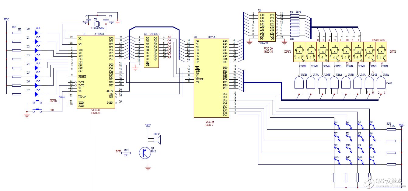
1. Interface:
The P1 port of 89S51 is connected to 8 small LED lights;
P3_2 of 89S51 is connected to the buzzer (low level sound);
Expand a piece of 8255:
The P0 port of the 89S51 microcontroller is multiplexed with the low 8-bit address and data. Now we use 74HC373 to separate the address. The P2_0 (A8) of the high-order address of the 89S51 is connected to the chip select terminal (/CS) of the 8255. The low-order address Q1Q0 (A1A0) and A1A0 of 8255 is connected, data bits P0_7~P0_0 are connected to D_7~D_0 of 8255 respectively. The addresses of port 8255 obtained from this are:
PA: xxxxxxx0 xxxxxx00 takes 0x0fefc; PB: xxxxxxx0 xxxxxx01 takes 0x0fefd;
PC: xxxxxxx0 xxxxxx10 takes 0x0fefd; CTL: xxxxxxx0 xxxxxx11 takes 0x0feff;
The PA port of the 8255 controls the 8 display segments of the LED digital tube; the PB port is respectively connected to the common anode of the 8 LED digital tubes;
The PC ports are respectively connected to the row and column lines of the 4x4 matrix keyboard.
2. Storage allocation:
struct{ //Alarm clock hour, minute, second, a total of 6 alarm clocks (initial state default: 00-00-F1)
uchar hour;
uchar minute;
uchar isON;
}alarm[6]={{0, 0, 0}};
uchar hour=12, minute=0, second=0;//hour, minute, second
uchar temp_second; //Used to switch the display time/date immediately
uint year=2011;// year
uchar month=12;// month
uchar day=1; // day
uchar week=6;// week
uchar Mdays[]={0, 31, 28, 31, 30, 31, 30, 31, 31, 30, 31, 30, 31};//Number of days in each month
uchar alarm_isON=1; //Alarm master switch
uchar alarm_staTIon=0; //alarm clock status
uchar ano; //alarm clock number (alarm clock number when the current time arrives)
uchar start_minute;//The time to start ringing (that is, the time of the set alarm clock)
uint count_ms25=0; //software counter (count 40 25 milliseconds for 1s)
uchar show_model=0; // Display mode: [0] switch display time/date [1] switch display date/time
const uchar fixTIme=0x00;//Time correction amount
uchar key=0xff;//The current key value obtained
uchar last_key=0xff; //The last key scanned (not 0xff)
uchar key_count=0;//Number of scans to the same key
uchar Edown=0; //Whether the alarm key is pressed
uchar led_buf[8]={24, 24, 24, 24, 24, 24, 24, 24}; //Time and date display buffer
uchar code led_table1[]={0x0c0, 0x0f9, 0x0a4, 0x0b0, 0x99, 0x92, 0x82, 0x0f8, 0x80, 0x90,
0x88, 0x83, 0x0C6, 0x0a1, 0x86, 0x8e, 0x40, 0x79, 0x24, 0x30, 0x19, 0x12, 0x02, 0x78, 0x00, 0x10,
0x08, 0x03, 0x46, 0x21, 0x06, 0x0e, 0x7f, 0x0bf, 0xff};//Digital tube segment code
uchar code KBTable[] = {'1', '2', '3', 'F', '4', '5', '6', 'E', '7', '8', '9' , 'C', '0', 'A', 'B', 'D'};//Key value (optional)
Five, software flow chart and description
1. Flowchart:
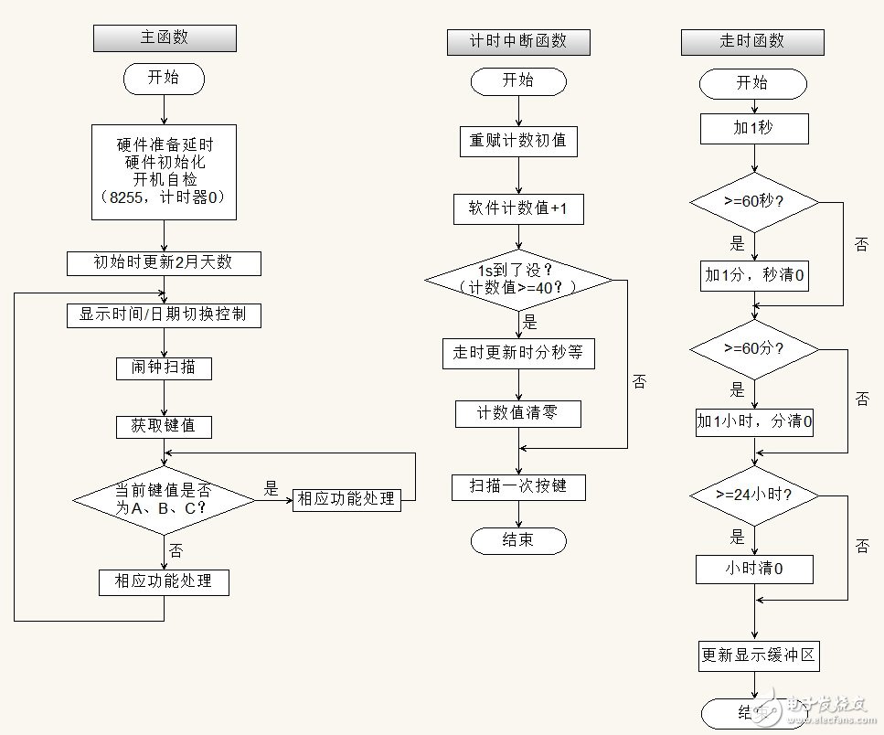
2. Main program segment description:
(1) Display:
void LED_show(uchar buf[])
{
uchar i, num, pLED=0x80;
for(i=0;i<8;i++)
{
num=buf[i];
PA=led_table1[num]; /*Send field code*/
PB=pLED; /*Send word bit code*/
pLED》》=1; /*Shift right by one*/
Delay(1); /* Delay */
}
}
(2) Keyboard (this design implements the following two scanning methods):
a. Row scanning method: send low-level signals from the first to the last row line in turn, if the key connected to the row line is not pressed, the port connected to the column line will get all "1" signals , if any key is pressed, it will get non-all "1" signal.
/*Keyboard scan (line scan method, delay debounce) ************************************ ********************
uchar code KBTable[] = {
0xEE, '1', 0xDE, '4', 0xBE, '7', 0x7E, '0',
0xED, '2', 0xDD, '5', 0xBD, '8', 0x7D, 'A',
0xEB, '3', 0xDB, '6', 0xBB, '9', 0x7B, 'B',
0xE7, 'F', 0xD7, 'E', 0xB7, 'C', 0x77, 'D',
0x00, 0xff};
uchar Get_key(void); // Get the final key value
{ uchar i;
uchar line, row, k_value;
staTIc uchar lastkey=0xff;
CTL=0x88; //CH input, CL output 10001000
PC=PC & 0xf0; // PC0~PC3 output 0, input PC4~PC7 (default 1 without key press)
if ((PC & 0xf0) == 0xf0)
{
lastkey=0xff;
return 0xff; //no key pressed
}
row = PC;
Delay(4); // Delay, eliminate jitter
if (row != PC)
{
lastkey=0xff;
return 0xff; // judged as jitter
}
line=0xFE;
for (i=0;i<4;i++)
{ PC = line; //Output scan signal
row=PC; //read keyboard port
if ((row & 0xf0) != 0xf0)
break;
line=(line<<<1)+1;
}
if (i==4)
{ lastkey=0xff; return 0xff; }
k_value = (row & 0xf0) "(line & 0x0f);
for (i=0; i<32; i+=2)
if (k_value == KBTable[i])
break;
if(lastkey==KBTable[i+1])
return 0xff;
lastkey=KBTable[i+1];
return KBTable[i+1];
}
b. Line inversion method: The line inversion method is also a common method for identifying closed keys. This method is faster than row scanning, but requires external pull-up resistors for row and column lines in hardware. First use the row line as the output line, the column line as the input line, the row line outputs all "0" signals, read the value of the column line, then the value on the column line where the closed key is located must be 0; then output from the column line All "0" signals, and then read the input value of the line, the line value where the closed key is located must be 0. Thus, when a key is pressed, a unique pair of row and column values ​​must be read. From this pair of row and column values, the position of the closed key can be found.
//One keyboard scan (line inversion method, interrupt scan count debounce) ******************************** ************************
uchar code KBTable[] = {'1', '2', '3', 'F', '4', '5', '6', 'E', '7', '8', '9' ,'C','0','A','B','D'};
//key_index 0 1 2 3 4 5 6 7 8 9 10 11 12 13 14 15
uchar key_scan(void) //return '0', '1', '2'. ..'E', 'F', 0xff
{ uchar key_index, temp=0;
CTL=0x88; //CH input, CL output 10001000
PC=PC & 0xf0; //Set the lower four bits to 0
if (PC!=0xF0) //Determine whether the button is pressed, if the button is pressed, it will pull down one of the ports in CH
{
temp=PC; //Read PC port
temp=temp&0xf0; //mask the lower four bits
temp=~
Shenzhen Ruidian Technology CO., Ltd , https://www.wisonen.com