![<?echo $_SERVER['SERVER_NAME'];?>](/template/twentyseventeen/skin/images/header.jpg)
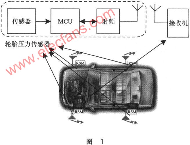
The TPMS system consists of a pressure sensor module and a central receiver. A pressure sensor module composed of a pressure sensor SPl2, a microcontroller and a 433 MHz transceiver IC (nRF401) completes the task of collecting and transmitting tire pressure.
In the future, installing a tire pressure monitoring system (TPMS) will also be an inevitable development trend like ABS and airbags. The tire pressure monitoring system monitors the pressure in the tires around the clock, and alarms the tires for air leakage and low and high pressure, so that the vehicle is always in a safe operating state.
1 System design
The TPMS system consists of tire pressure sensors and receivers. The tire pressure sensor uses MicrochiP's PICl6F628A low-power 8-bit MCU, the pressure sensor uses Infineon's SPl2, and the radio frequency IC uses N0rdic's nRF40l.
The pressure sensor installed in the tire transmits the pressure and temperature information in the tire to the receiver in the cab, letting the driver know the air pressure in the tire at any time, as shown in Figure 1.
1.1 RF circuit
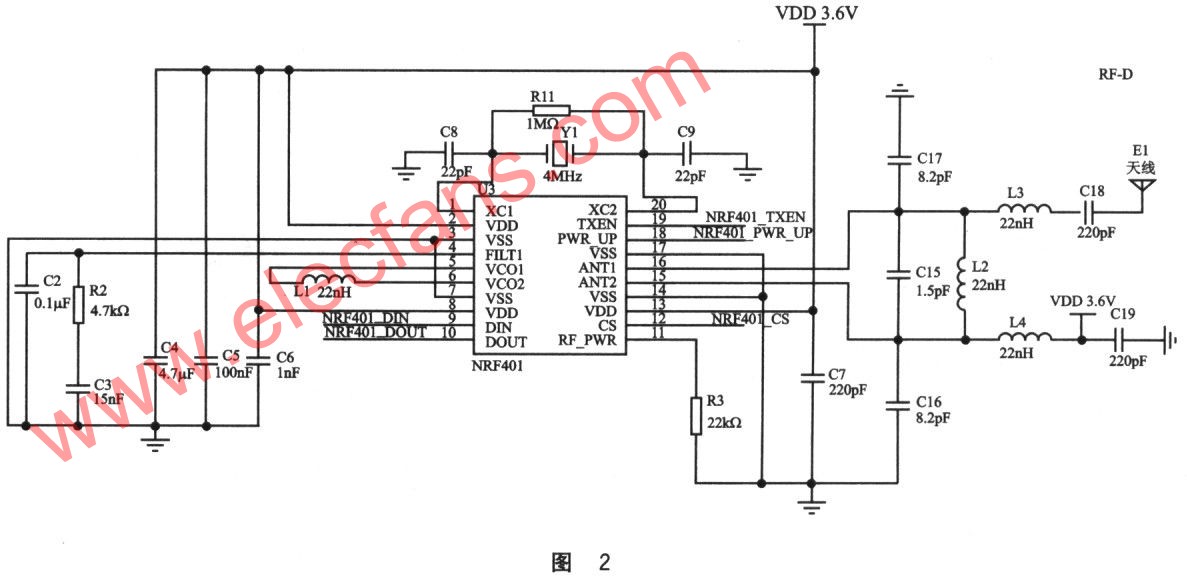
In the radio frequency signal circuit shown in Figure 2, the Nordic, Norway's nRF40l device is used, which is a monolithic UHF wireless transceiver IC in the 433 MHz ISM band. It uses FSK's modulation and demodulation technology, its maximum operating rate can reach 20 kb, the transmit power is adjustable, and the maximum is 10 dBm. The basic technical indicators are as follows:
The center carrier frequency point is 433.92 / 434.23 MHz;
Maximum transmit power is 10 dBm
Working voltage is 2.7 ~ 5.25V;
The current consumption when receiving is 250μA, the maximum is 28 mA when transmitting, and the standby current is 8 / μA.
NRF401's ANTl and ANT2 are antenna input / output multiplexing pins. In input mode, the RF signal is demodulated by connecting this pin to a low-noise amplifier; similarly, in output mode, the modulated signal is output through this pin after power amplification.
Pin 4 is the input of the PLL phase-locked loop filter of nRF401. The voltage of this pin during normal operation is l.lV0.2V.
Pin 5 and pin 6 are the peripheral circuits controlled by the piezoelectric crystal. These two pins are indirectly connected with a 22μH inductor with a value of Q> 45 @ 433 MHz.
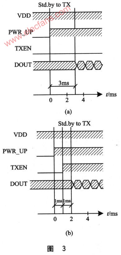
Pin 7 and pin 8 are the data input pin and output pin, respectively. Cooperate with the potential sequence on the 18-pin PWR_UP and 19-pin TXEN to complete the sending and receiving of information. Figure 3 is a timing diagram for controlling the operation of each pin during data transmission and reception.
11 feet external RF power control resistor. As R3 in Figure 2, the value is between 22 and 100kΩ. It usually reaches 7 dBm around 30kΩ.
1.2 Structure of spiral antenna
Since there are different types of antennas, they should be selected according to specific application requirements. In this application, the antenna is located in the hub of the car. Close to the valve. During high-speed driving, the antenna continuously changes direction. In order to enlarge the receiving angle as much as possible, the helical antenna is selected.
The number (N), diameter (D) and distance (S) of the spiral antenna determine the gain and directivity of the antenna.
The total length of the antenna is LN = NLO = Nsqit (S2 + C2) where C = xD is the circumference of the spiral, and Lo = sqrt (S2 + C2) is the length of a circle of wire.
Another important parameter is the helix angle α, which is the angle between the tangent of the helix and the vertical plane of the helix axis. The definition of the helix angle is that α = tan-1 (S / C) helix antenna has the following two working modes.
①Normal mode. In the normal working mode, the antenna radiation field has a maximum value in the normal plane relative to the spiral axis. For this mode: NLo << λ.
â‘¡Axial (endfire) mode. This working mode has only one main lobe, its maximum radiation intensity is along the spiral axis, and there is an inclination angle between the auxiliary office and the axis. To stimulate this mode, its diameter D and space 3 must be a large fraction of the wavelength.
1.3 Sensor circuit
SPl2 is Infineon's tire pressure sensor IC.As shown in Figure 4, the pressure, temperature, acceleration, and voltage detection circuits are integrated through MEMS technology, and the indication values ​​of each physical quantity are directly output in digital form. Interact.
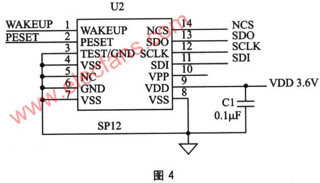
At the same time, there are two internal clock signals, WAKEUP and RESET. WAKEUP outputs a pulse signal every 6s, RESET outputs a pulse signal every 54 minutes, low electron is effective.
1.4 System power consumption
Because the overall quiescent current of the TPMS system is required to be less than 20μA, it is necessary to ensure that the selected device must be a low-power or ultra-low-power chip. The quiescent current of PICl6F628A is 0.1μA, the quiescent current of sensor SPl2 is 0.6μA, and the standby current of radio frequency NRF401 is 8μA.
After actual measurement, the static power consumption Ist = Ist_mcu + Ist_sensor + ist_rf + Ist_cap = 15μA. Ist_cap is the leakage current of the tantalum capacitor. The dynamic power consumption is 25mA (maximum value) when the radio frequency is continuously transmitted.
2 Software design
2.1 Overall software design
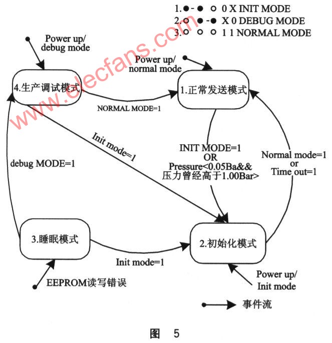
The software is divided into 4 operation modes: debug mode (for factory diagnosis), initialization mode, sleep mode (sleep) and measurement mode.
(1) Debug mode
Mainly perform some internal testing and diagnostic functions of the products leaving the factory. The body includes two parts: sensor test and radio frequency test.
(2) Initialization mode
Receive the ID code and level judgment threshold given by the host.
(3) Sleep mode
Operate with the lowest power consumption and respond to the operating requirements of the system.
(4) Measurement mode
The measurement mode mainly completes the following functions:
â‘ Regularly measure tire pressure and temperature;
â‘¡When the pressure is alarmed in areas of different levels, the same level will only be reported once;
â‘¢ No change in pressure, report pressure and temperature once at a fixed interval;
â‘£ Guarantee system reliability. The system is reset every about 1 hour.
⑤Alarms of different levels appear at the same time, then give priority to high temperature, high pressure and low pressure levels.
Their mutual conversion relationship is shown in Figure 5.
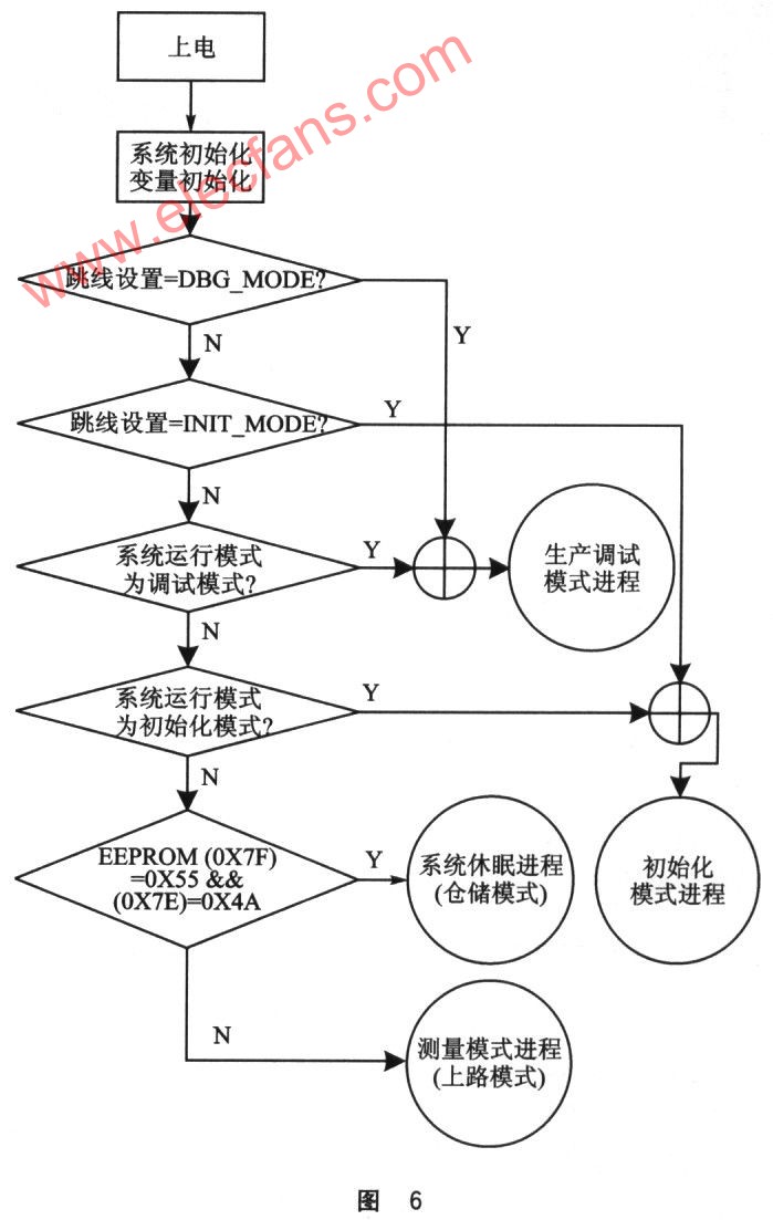
The working flow chart of system power-on reset is shown in Figure 6.
2.2 Processing of sensor data
SP12 is a pressure-sensing IC, which directly processes the obtained digital quantity. It only needs to send the corresponding command words and instructions to it through the SPI physical interface to get the current tire pressure, temperature, acceleration and other values. Because the PICl6F628A has no SPI module, the SPI driver can be simulated here through software. To achieve the purpose of communication with SP12.
2.3 Processing of RF data
In order to ensure the reliability of sending and receiving data in a harsh environment, and according to the characteristics of the small amount of information and simple data in this application, the method of information redundancy is used to ensure the reliable reception of data, that is, the continuous transmission of the same content of information.
The data transmission processing uses the USART module inside the MCU.
The data frame format is preamble + sync character + ID code + pressure + temperature + alarm bit + check code.
Data receiving and processing, nRF40l in the receiving mode, DOUT pin has continuous random signal input, how to efficiently filter out the sent information in the byte stream? Here, because the sending format is fixed, it is used in the interrupt processing process In the way of finite state machine.
Conclusion
The TPMS system has the characteristics of small size, low cost and bidirectional golden time, and is widely used. For the country with tens of millions of cars, it will have a very broad market prospect. This will set off a new wave of automotive pressure sensor applications.
Travel Charger Adapter is convenience for these people who always travel in many countries. Desktop Power Adapter have normal DC connector for your need, and wall power adapter have mutil plug, like US/UK/AU/EU etc. We also can produce the item according to your specific requirement. The material of this product is PC+ABS. All condition of our product is 100% brand new.
Our products built with input/output overvoltage protection, input/output overcurrent protection, over temperature protection, over power protection and short circuit protection. You can send more details of this product, so that we can offer best service to you!
Travel Charger Adapter,Portable Travel Charger Adapter,Mini Travel Charger Adapter,Travel Charger Supply
Shenzhen Waweis Technology Co., Ltd. , https://www.waweispowerasdapter.com