![<?echo $_SERVER['SERVER_NAME'];?>](/template/twentyseventeen/skin/images/header.jpg)
Electronic enthusiasts provide you with the circuit diagram of the wireless mouse design, I hope it can help you!
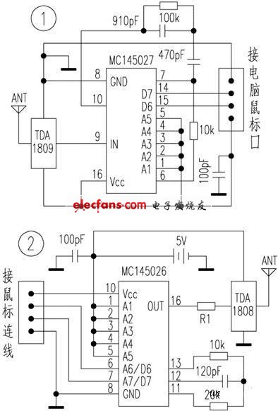
The device uses the codec circuit MC1450226 / MC145027 and the RF transmit / receive module TDA1808 / TDA1809 to cooperate with each other, and can flexibly manipulate the mouse within the range of 10 to 120m, and it does not need to make any changes to the appearance and internal circuit of the original mouse during production. It conforms to the operation habit, is convenient and reliable, and is very suitable for enthusiasts to make their own.
Under normal circumstances, there are 4 circuit cables inside the cable between the mouse and the computer (the circuit device can accept up to 4 data lines, and the reader can choose according to the actual situation of his mouse), which are the power supply positive pole, power ground, and data line. 1. Data cable 2. We cut the mouse connection to find these four lines, and use the data transmission terminals D6 and D7 of the MC14650 encoding circuit to receive the data from the mouse data line 1 and data line 2 and encode them inside the chip and pass the RF transmission module. TDA 1808 was launched.
After the RF transmitter module TDA1809 works, it will input the received coded information into the MC1450727 decoding circuit. After its conversion, the signals of the original mouse data line 1 and data line 2 will be restored at the chip data output terminals D6 and D7. The computer cable is sent to the computer.
It can be seen that the above circuit does not need to modify the mouse and computer, and does not need to install additional mouse driver software. All functions of the original mouse can also be used normally.
This circuit (see Figure 1 and Figure 2) can work without debugging as long as the selected components are normal.
Bee Eyes Beam Light ,Mini Bee Eye Moving Head,Bee Eye Led Moving Head,Bee Eyes Beam Lights
Guangzhou Cheng Wen Photoelectric Technology Co., Ltd. , https://www.cwledwall.com