![<?echo $_SERVER['SERVER_NAME'];?>](/template/twentyseventeen/skin/images/header.jpg)
Introduction:
This article refers to the address: http://
Due to the proliferation of mobile devices such as smartphones and tablets, power consumption must be reduced in order to extend battery life. So far, the focus has been on the processor, which is the most power-hungry device on the board. There is a new demand for low power audio products in the market. But mobile devices are basically a multimedia consumer device. In the past (about the beginning of the 20th century), the main function of the phone was the phone – the time spent using the audio signal path was very small in terms of device usage time. Therefore, since the audio signal path does not have a large impact on the overall power consumption of the device, its power consumption is not important. In contrast, tablets/smartphones are currently the primary device for audio/multimedia consumption (music, movies, radio, audiobooks, etc.) and the market power to drive low-power audio solutions. This article will briefly review the history of audio amplifiers and current state-of-the-art audio amplifiers, and then describe the novel architecture and circuit technology used by Nuvoton's next-generation ultra-low-power audio amplifiers.
Development status:
Until the late 1990s, audio amplifiers used the well-known EE101 Class A, Class B, and Class AB analog amplifier topologies. For specific applications, the choice of engineering topology is determined by trade-offs between performance (THD, etc.), power consumption, and cost. Power consumption ranges from a minimum of 25% (Class A) to a maximum of 78.5% (theoretical) achieved by sacrificial performance (Class AB). Since the terminal device is mainly AC power (receiver, portable stereo recorder, TV), power consumption itself is not a big problem.
In the mid-1990s, a variety of market forces merged to put higher demands on the power consumption of audio amplifiers. For high-power terminals, home theater is becoming more and more popular. To achieve six high-power paths with low power consumption, you need to use huge power supplies and large heat sinks, and consider the cost and form factor associated with them. At the same time, flat-panel TVs debuted in the market for the first time. The selling point of this kind of TV is "light and thin", and there is no space to install a heat sink to dissipate heat for too much power. And in the past decade, the advent of mobile phones and iPods has placed higher demands on battery life. All of these market developments require audio amplifiers to have lower power consumption without affecting audio performance. The answer is a new class of amplifiers - Class D amplifiers. Class D amplifiers are claimed to have a theoretical power of 100% and an actual efficiency of over 90%. Although Class D topologies have been around for decades, mainstream applications still need to consider cost, performance and EMI issues, so they are limited to the high-end subwoofer market.
A typical plot of the power dissipation and rated output power of a 10 W amplifier is illustrated in Figure 1 below.
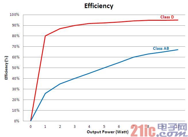
Figure 1: Graph of output power and efficiency for Class AB and Class D (10 W amplifier)
Whether it's to save power or achieve a smaller form factor, the benefits of Class D make it the preferred topology for markets that require low power. The first generation of Class D technology has been widely used, making some shortcomings of the topology and new methods to overcome these shortcomings become the focus of the industry.
Class D Amplifier Topology
The most basic class D amplifier topology uses pulse width modulation (PWM) and triangular wave (or sawtooth) oscillators. Figure 2 shows a simplified block diagram of a half-bridge Class D amplifier. It includes a pulse width modulator, two output MOSFETs, and an external low pass filter for recovering the amplified audio signal. The MOSFET is alternately connected to the output node and ground and can be used as a current-steering switch. Since the output transistor switches the output to VDD or ground, the final output of the Class D amplifier is a high frequency square wave. Most Class D amplifiers typically have a switching frequency of 250 kHz to 1 MHz. The input audio signal is compared to an internally generated triangular wave oscillator, and the pulse width of the output square wave is modulated by inputting the audio signal. The resulting square wave duty cycle is proportional to the level of the input signal. When there is no input signal, the duty cycle of the output waveform is equal to 50%, which increases or decreases in proportion to the input signal.
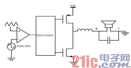
Figure 2: Class D amplifier in half-bridge mode
Class D amplifiers also use a full bridge output stage. The full bridge circuit uses two half-bridge output stages and drives the load differentially. This type of load connection is often referred to as a bridged load (BTL). As shown in Figure 3, the full bridge structure works by switching the conduction path of the load. Therefore, the load current can flow in both directions without the need for a negative supply or a DC blocking capacitor.
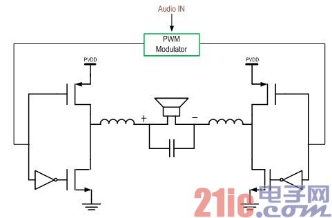
Figure 3: Class D amplifier in full bridge / BTL mode
Disadvantages of traditional Class D amplifiers:
1 Fixed switching losses result in higher quiescent currents, resulting in lower power output. Class D amplifiers are essentially switching circuits. Under their basic architecture, they switch between ON and OFF based on the mode in which the audio signal is encoded. The switched output is transmitted to the load (speaker) through a low pass filter to recover the amplified audio signal. See Figure 3 above.
In theory, since the state of the output device is not ON or OFF, the switch does not cause the power to drop, and all power is transferred to the load (the efficiency is 100%). In practical applications, the switch is implemented by a MOSFET and a finite resistor (drain-source on-resistance). The lower the drain-to-source on-resistance, the higher the efficiency. A typical speaker with an 8 Ω resistor in a bridge configuration (half bridge) and a 0.4 Ω drain-to-source on-resistance provides approximately 90% efficiency. (See Figure 2). However, a low drain-to-source on-resistance means a larger mobile device, and vice versa means a higher input capacitance. The capacitor needs to be charged/discharged each time it is switched, resulting in higher switching losses (this loss is not as significant as the loss in the analog amplifier topology). To make matters worse, in a broad sense, this loss is “fixed lossâ€, independent of the input signal. In fact, since the switching amplifier performs switching even without any signal, the fixed loss is the constant loss of the power supply. In fact, although Class D amplifiers have an efficiency of 90% at full power, fixed losses can greatly reduce the efficiency at low power. This has become a problem in practical applications, not just sine waves at full power. Music from different genres has 6-10 crest factors, and most of the sounds heard are emitted at low power, thus reducing the efficiency of the amplifier.
2 EMI Filtering - A well-known disadvantage of Class D amplifiers is that they act as switching amplifiers with electromagnetic interference that interferes with AM band and handset reception. This problem is currently solved by using filters and packaging the output switching devices and output filters with metal housings in high power applications.
3 BOM Cost - Traditional Class D architectures require a low pass filter to recover the amplified audio signal. This will increase the BOM cost of the amplifier system. Many manufacturers have made the latest advances to provide filterless Class D amplifiers, but generally at the expense of reduced performance or increased EMI.
A new generation of Class D amplifiers:
Engineers at the Xintang Technology Silicon Valley R&D Center took the lead and worked through two years of intensive efforts to address the shortcomings described in the previous section. They use global resources to investigate various possible solutions to define and design a new generation of Class D amplifiers. The IC block diagram is shown in Figure 6 below. The new class D amplifier series introduced by Nuvoton Technology, the NAU series, adopts the design idea of ​​this technology and circuit (patent pending). The following is a brief technical description of the innovative approach to solving the Class D problem adopted by Xintang Technology:
1 Low Quiescent Current – ​​The NAU series sets a new standard for providing ultra-low quiescent current for output power. The NAU8223 is a 3 W stereo Class D amplifier with quiescent current of 1.1 mA per channel. Currently, the industry's quiescent current averages 3 mA per channel!
2 Excellent EMI performance and filterless architecture - The NAU8223 and NAU8224 stereo 3 WD class audio amplifiers eliminate the need for an external output filter and provide excellent EMI performance, as shown in Figure 5 below. Nuvoton's Class D amplifiers use BD modulation (also known as ternary or filterless modulation). With BD modulation, the phases of the two speaker driver outputs cancel each other out. Under BD modulation, the two comparators receive the same carrier signal (in phase) and the input signals are out of phase. As shown in FIG. 4, one comparator receives the input signal INP and the other comparator receives the out-of-phase signal INM. Both are compared to the same reference waveform VREF. OUTM and OUTP are two speaker outputs that drive the speaker in a BTL (Bridge Load) configuration. Therefore, when there is no signal at any input, the output average voltage is very close to zero. When the signal is in a positive cycle, the duty cycle of one speaker output is greater than 50% and the other is less than 50%. When the input signal is in a negative cycle, the duty cycle of the output is reversed. Therefore, in general, during switching operation, the output voltage on the load is zero, thereby reducing output current and power consumption. Due to the low switching power consumption, the speaker can be used as its own LC filter, eliminating the need for an additional LC filter. Switching frequency components still exist, but because of their higher frequency, the speakers provide very high impedance and their losses are greatly reduced and are not heard.
In addition, the NAU8223 and NAU8224 have excellent interference immunity and excellent PSRR (greater than 85 dB at 217 Hz), making them ideal for Class D audio amplifiers in wireless and AM band applications.
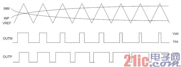
Figure 4: BD modulation scheme waveform
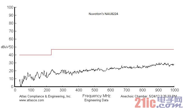
Figure 5: Nuvoton NAU8223/NAU8224 stereo 3 WD RF transmission with 30 cm wire
3 Anti-Clip Control - This function is used to control the output for maximum output level without distortion. The anti-clipping function is enabled when the input loads a large input signal that causes clipping and distortion. The anti-clipping function reduces the gain of the amplifier to an appropriate value so that no clipping is caused at the differential signal output. The anti-clipping function simultaneously monitors the supply voltage to ensure that clipping is not caused by changes in the supply voltage. This results in a significant improvement in sound quality and protects the speaker from damage.
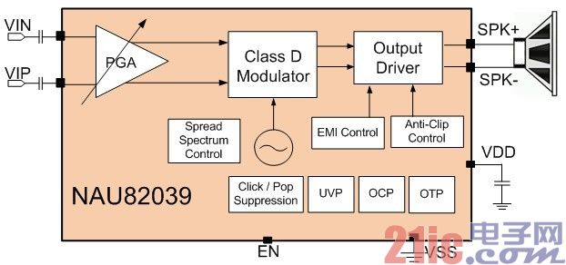
Figure 6: Mono Class D Amplifier
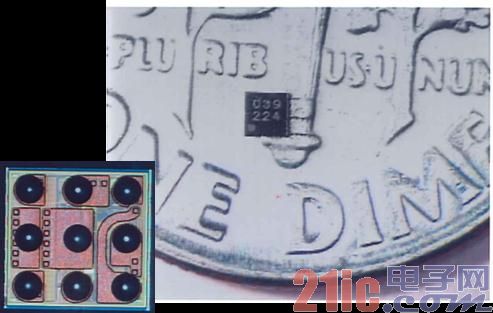
Figure 7: Mono Class D in WLCSP Package
Looking to the future:
With the rapid development of mobile platforms and the emergence of mobile phones as the primary delivery device for audio content, the entire audio signal path (not just amplifiers) has a continuing market demand for low-power audio solutions, providing new semiconductor solutions for these needs. The power.
Iphone Screen Protector,Tempered Glass,Privacy Tempered Glass,Hydrogel Screen
Shenzhen TUOLI Electronic Technology Co., Ltd. , https://www.hydrogelprotectors.com