This article refers to the address: http://
In the home alarm system, industrial monitoring, intelligent community, because the original system can only collect relevant data, and then transmit it according to a proprietary or specific network. In applications, users often reflect two major drawbacks. First, you can't see the live image. Second, monitoring is limited to a specific private network, such as through a local area network, a telephone network, a video line monitoring network, and the like. Therefore, the demand for webcam via the Internet is very urgent.
1 system composition
The structure of the network camera system is shown in Figure 1. MEl010 is a 100 megapixel CMOS image sensor chip, and the Rabbit3000 module is based on a Rab-bit 3000 microcontroller. The MCU is based on the Z80 core. The maximum clock frequency is up to 54MHz. There are 6 high-speed serial ports and 56 I/O ports. It directly drives 512KB SRAM and 512KB Flash. When the network is transmitted through the Ethernet interface. The TCP transfer rate can reach 6Mb/s. The Dynamic C development tool provided by Z-World of the United States provides TCP protocol stack function support, as well as C, assembly and mixed programming functions, which is very suitable for network applications.
The network camera implements the following functions: Directly drives the MEl010 CMOS camera chip for image processing and image processing, and a built-in mini WEB server allows users to access WEB pages on the Internet. Static image capture via the CGI interface, such as adding a SOCKET interface, can also capture dynamic images through the Activex control. Two image formats of 160×120 color and 320×240 black and white can be selected.
2 CMOS camera chip control
2.1 The structure of MElO1O and the MElOlO CMOS image sensor chip of Nanjing Weimeng Electronics can capture 352×288 color and black and white images. The internal functional block diagram is shown in Figure 2.
The working principle of the chip: sampling control through the Samp and SampG feet, that is, taking images. After the shooting, the chip stores the analog voltage of each point in the image into the buffer to form a maximum 352×288 pixel data array. The microcontroller can access the image buffer point by point by changing the row and column address ADR (8..O). The image buffer actually stores the photo-induced voltage of each pixel into a small capacitor. By inputting a clock pulse at the ADC Clk pin, MElO1O performs analog-to-digital conversion during the low period of ADCclk, and outputs a rising edge. Then the microcontroller can read the pixel data of the corresponding row and column address from the data port ADCount (7~0). The row and column addresses share 9 address lines, and the pulses generated by the XYSEL pin are switched.
Having an image buffer is the biggest feature of MElO1O. Generally, CMOS Sensors must use CPLD to send image data to RAM for storage at a very fast speed, usually about 13MB/s, and then read by the microcontroller, so the interface is more complicated. This feature of MElO1O allows Rab-bit3OOO to be read directly, combined with the powerful network functions of Rab_bit3OOO, thus forming a unique network camera.
The shooting timing is shown in Figure 3.
2.2 Image reading makes the Rabbit1, PF (7~O) of Rabbit3OOO and MEIOIO address line ADR(8~O), PA(7~O) and data line ADcount(7~O), PB7 and modulus The conversion clock ADCclk is connected. Now, in a behavior example of reading a 16O×1 2O color image, the reading process is introduced, and the program is implemented by assembly to speed up the image reading speed. The read image timing is shown in Figure 4.
#asm debug
Readoneline:: ; read a row of data; read to linbuf 1d hl, linebuf; pointer hl points to linebuf
Ld de, 16O; a row of 16O pixels ld C,
Rp _read:
:ADC clk
Ioi lda, (PBDR); generate ADC clock res O, a
Ioi ld(PBDRl,a
Set O,a
iOi ld (PBDR), a
Ioi lda, (PADR)
; read data from PA ld (hl), a
; read the data into linbuf, pointer hl points to the corresponding bit of llnbuf inc hl; pointer moves down inc c; counter plus 1
Ld a,c
Ioi ld (PFDR), a; address plus 1
Dec de ; read 160 pixels jr nz, rp_read: otherwise read the next ret
#endasm
3 image processing
3.1 Elimination of FPN
Since the CMOS image sensor generates FPN (Fixed Pattern Noise), MElO1O requires software to perform noise cancellation processing. Otherwise, the surface of the captured image will be superimposed with many fine color points. The position and size of these noise points are fixed. It is determined by the CMOS image chip and the circuit itself.
The method of FPN elimination is to take an image with an exposure time close to O before the official shooting. Due to the presence of FPN, although the sensitization is close to O, the image is not a uniform black photo, but some color will appear. Noise point. This image is stored in memory, and as a reference, an image is subtracted from this reference image, thereby eliminating FPN.
3.2 Color interpolation readout and the data after FPN elimination is actually RGB array, MN1O1O achieves color function by RGB color filter on the photosensitive surface (optional, if there is no filter is black and white chip), filter The arrangement is shown in Figure 5. This is the Mosaic Bayer filter used by the general image sensor. From the O line, the even lines are arranged as RGRGRG... The odd lines are arranged as GBGBGB...
Therefore, the data of each point represents only one color light intensity value (gray value) of the point, and the colorization interpolation processing is also performed according to the corresponding algorithm. Using the information of the surrounding pixels, "guess" to calculate the other two color light intensities that the point "should" have, thereby obtaining a complete RGB value, constituting a 24-bit true color image. This color interpolation method is used to achieve the "near" true color processing method. Although the image quality is not as good as the true (R, G, B) three-group pixel type color imaging technology, it can already satisfy the usual image detection. need.
The algorithm example is as follows:
Let i, j be the number of rows and columns respectively. When Ri, j has i%2==O&&j%2==0, the algorithm is R=Ri,j
G=(Gri,j-1+Gri,j+l10 Gbi-1,j+Gbi+l,j)/4
B=(Bi-i,j-1+Bi—I,j+1+Bi+l,j-1+Bi+l,j+1)/4
The corresponding Rabbit program of Rabbit3OOO is form_rfgb(){
...
}
3.3 Embedding the image to the HTTP server After the RGB interpolation synthesis, the true color image can be obtained, but the complete image processing also needs to perform exposure control, γ correction, white balance adjustment and the like. The exposure control algorithm mainly calculates the average amount of brightness of each pixel. The self-balancing adjustment is due to the sensitivity of the CMOS sensor and the human eye to the RGB three-color light. Therefore, it is necessary to multiply the values ​​of the three pixels of R, G, and B by the scaling factor. ΥCorrect is mainly to adjust the contrast.
After obtaining the complete image data, add the BMP file header to form a newfile. The C program code is as follows:
Void makefile(){
Char newfilesize[4];
Newfilesize[0]=0x3a;file size newfilesize[1]=Oxe5;
Newfilesize[2]=O;
Newfilesize[3]=O;
Root2xmem(newfile, newfilesize, 4); set file size sspec_addxmemfile("/databmp", newfile, SERVE_RHTTP); embedded in HTTP server
4 HTTP server implementation It is not difficult to implement HTTP server through Rabbit3OOO-based module. Just use web design software such as Dreamwave, Frontpage, etc. to design a web page and then export it to the HTTP server of Rabbit3OOO module. Set the web page file name index.html, the web page contains the image ledon.gif, and the stored directory is samples/RCM32OO/pages. Use the following command to export the file to the HTTP server.
#Ximport"samples/RCM32OO/pages/index.shtml" index html
#Ximport"samples/RCM32OO,pages/ledon.gif"ledon_gif
In addition, you need to declare the file type HttpType http_types[] in the HTTP server and set the HTTP server to access files, variables, and the structure type of the function HttpSpec http_flashspec[].
The relevant code for running the HTTP server in the main program is as follows:
Main(){
Sock__init();
While(1){
HTTP_server();
}
5 Control shooting through the CGl interface Add the following definition in HttpSpec http_flashspec[]:
{ HTTPSPEC_FUNCTION, "/get_photocgi", O, get_hototoggle, O, NULL, NULL}.
Embed a button icon in the web page, assuming button. Gif, make it link to "/get_photocgi", when you click the button button on the web page, the program will jump to execute the following function:
Int get_hototoggle(HTTPState*state){
Get_hoto() ; take a picture cgi_redirectto(state,'data html'); jump to the data.html page,
; (This page contains the image file taken)
returnO:
}
You can see the captured image.
This article introduces the color image of 160×120 resolution as an example. Since the Rabbit3000 microcontroller directly drives limited memory, when the resolution is higher, such as 320×240, it is generally recommended to store black and white images, which can reduce the file size.
Conclusion <br> Combining image technology based on the Internet is a hot spot in the development of alarm systems, industrial control, and smart homes. There are mainly image processing solutions based on 8-bit microcontrollers, DSPs and ARMs. There are many similarities between the underlying image processing and the control of the CMOS image chip. Although based on DSP and ARM has the advantage of computing speed, but because Rabbit300 has powerful network support, encryption and I/O control, serial communication, data acquisition function, combined with MEl0l0's simple single-chip interface, it still has distinctive features. It is suitable for occasions where real-time image transmission is not demanding; and if combined with high-performance image chips, such as the Weiss GO7007 with MPEG4 compression, real-time image transmission can also be achieved. The content presented in this paper is based on the author's current smart community project, and has successfully developed a prototype.
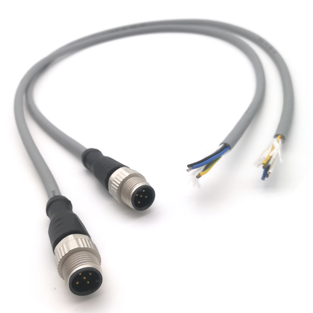
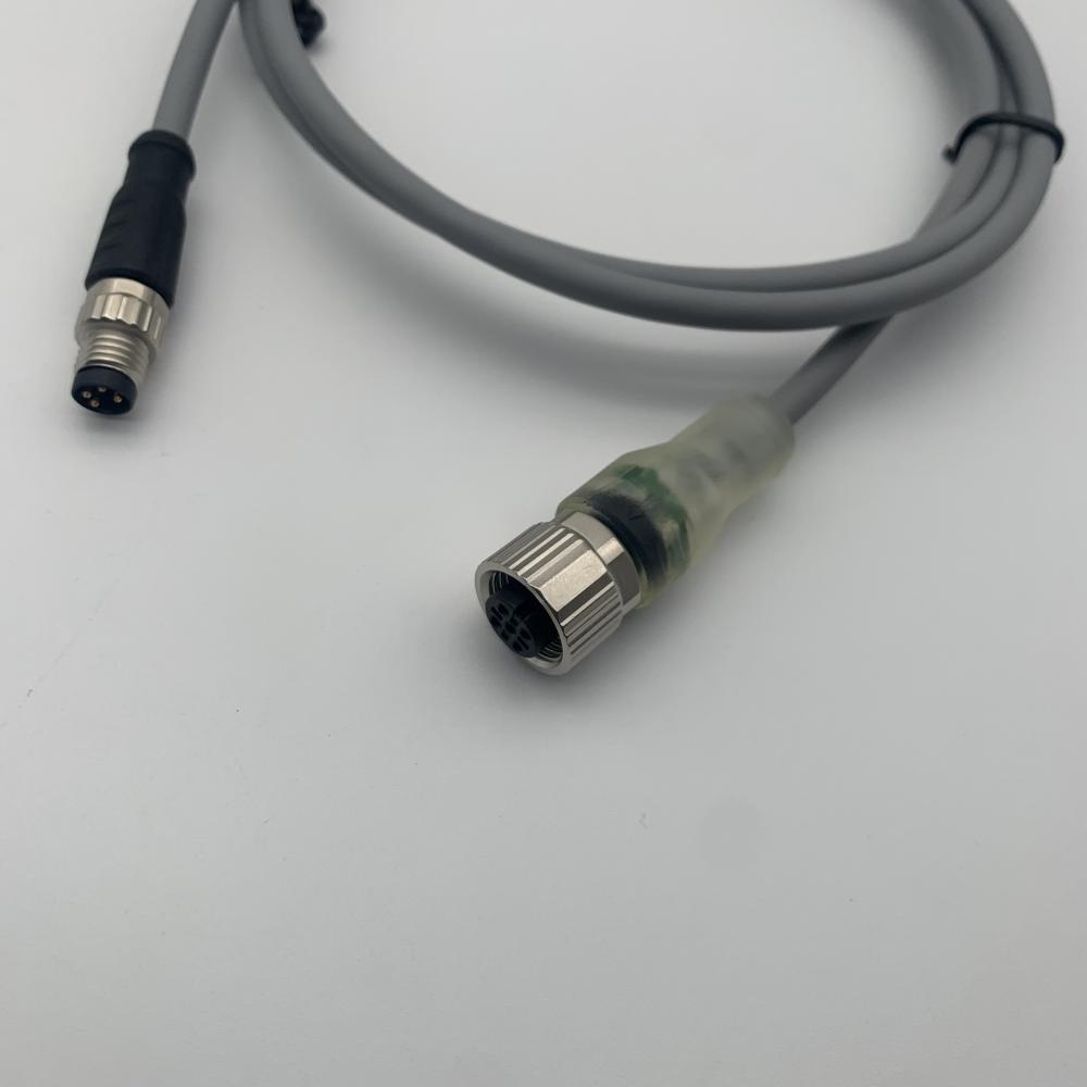
Connection cables widely used for connecting sensors and actuators . Based on different situations , we can provide M5 Connection Cable , M8 Connection Cable , M12 Connection Cable , 7/8" connection cable . For these cables , we can provide 3 to 17 cores .


Connection Cable,valve cable,M8 cable,M12 cable,7/8" cable
Kunshan SVL Electric Co.,Ltd , https://www.svlelectric.com
![<?echo $_SERVER['SERVER_NAME'];?>](/template/twentyseventeen/skin/images/header.jpg)