![<?echo $_SERVER['SERVER_NAME'];?>](/template/twentyseventeen/skin/images/header.jpg)
1) There is a circuit on the network that achieves a high-bandwidth bandpass filtering effect with a high R3/Req ratio. However, due to the GBW (Gain Bandwidth Product) limitations of the op-amp, the actual center frequency of the circuit ends up being lower than the calculated value.

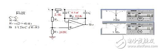
2) Another interesting circuit I found online is a complex 50Hz notch filter. After several simulations and analysis, I derived a simple formula for creating a notch at any desired frequency: fn = 1 / (2πC√(R2R)). By adjusting resistor R2, I was able to fine-tune the output waveform so that it perfectly matches the input. Then, by inverting the signal and using R3 to adjust the DC offset to zero, I achieved the best notch performance.
Using the original circuit parameters, the calculated notch frequency is: fn = 1 / [2π × 0.1e-6 × √(411e+3 × 2.4e+3)] = 50Hz.
If the capacitance is changed to C = 2μF while keeping other components the same, the new notch frequency becomes: fn = 1 / [2π × 2e-6 × √(411 × 2.4) × 1e+3] = 2.5Hz.
Although the GBW of the op-amp has minimal impact on the notch frequency itself, it can introduce a low-pass filtering effect on signals above the GBW limit, which may slightly affect the overall performance of the circuit.
3) Regarding the bandpass function using resistance
The previously mentioned band-stop circuit performs a differential operation, where the time constant of the inverting terminal determines the passband frequency of the circuit. When a sine wave at the notch frequency fn is applied, if R1:R3 equals Re:Rf (where Re and Rf are equivalent resistances corresponding to the transmission frequency), the differential output becomes zero, effectively canceling the fn frequency. However, when R3 is adjusted differently, the circuit begins to allow certain frequencies through, thus achieving a bandpass response.

Induction Coils,Electronic Eye Induction Coils,Rectangular Induction Coils,Induction Coils For Medical Industry
Shenzhen Sichuangge Magneto-electric Co. , Ltd , https://www.scginductor.com