![<?echo $_SERVER['SERVER_NAME'];?>](/template/twentyseventeen/skin/images/header.jpg)
0 Introduction Automotive durability testing is an important part of automotive testing. During the testing process, changes in driving behavior of test personnel often lead to inconsistent experimental results, which reduces the effectiveness of experimental data. Therefore, major automobile companies have successively adopted driving robots instead of testers for vehicle testing. Testing with a driving robot is important for reducing human labor intensity, reducing the damage of the test environment to the test personnel, improving the test efficiency, the objectivity and accuracy of the test results, saving the test cost, and accelerating the progress of the automobile research and development.
In order to test the reliability of the driving robot and the driving algorithm, a simulated driving system must be available to meet the requirements of the driving robot. The model vehicle wireless control system designed in this paper is the main link to realize the robot simulation driving, and provides an experimental platform for the driving robot and its driving algorithm.
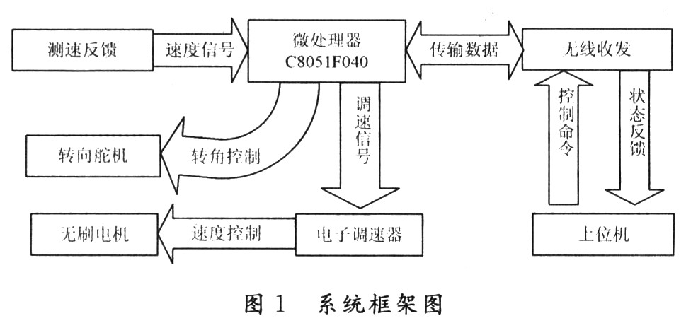
The system adopts a 1:10 electric model car. The speed adjustment is completed by an electronic governor and a brushless DC motor. The steering of the front wheel is controlled by the steering gear to complete the steering of the model car. The control signal of the upper computer is transmitted to the control core C8051F040 via the ZigBee wireless transceiver module, and the single chip transmits the corresponding PWM signal to the electronic governor and the steering servo according to the motion command of the upper layer to realize the control of the model vehicle motion.
This article refers to the address: http://
1 System framework The system adopts modular design and is mainly composed of single chip microcomputer, wireless transceiver module, speed feedback, electronic governor, brushless motor, steering servo and upper computer. As shown in Figure 1.
2 hardware design,
2.1 Wireless module hardware design The wireless transceiver module realizes the communication between the microprocessor and the host computer through ZigBee technology, and is the intermediate node between the host computer and the model vehicle motion control module. Through this module, the upper control command can be sent to the microprocessor, and the microprocessor feeds back the speed signal and the corner signal to the upper console.
This module uses the CC2431 chip introduced by TI. The CC2431 uses an enhanced 8051 MCU, 32/64/128 KB flash memory, 8 KB SRAM and other high-performance modules, and has a built-in ZigBee protocol stack and supports the 2.4 GHz IEEE 802.15.4/ZigBee protocol. Figure 2 shows the hardware circuit diagram of the wireless module, with the CC24.31 chip as the core. The antenna uses an unbalanced antenna. In order to make the antenna work better, an unbalanced transformer is used to connect the antenna. The balun is composed of resistors R1, R2, inductors L1, L2, capacitor C1 and PCB microwave transmission lines.
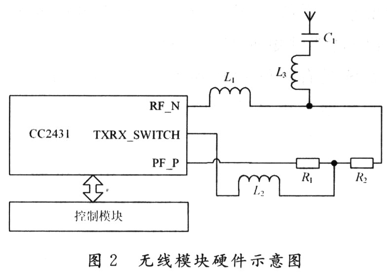
Wherein, the resistance of R1 and R2 is half of the wavelength of the electric wave, that is, λ/2. The inductance values ​​of L1 and L2 are 22 nH and 8.2 nH, respectively. They are not only part of the balun, but also provide the required DC offset for the on-chip low noise amplifier (LNA) and power amplifier (PA). The equivalent resistance of the entire antenna system is 50Ω, which meets the requirements of RF input/output matching resistors.
2.2 Control Module Hardware Design The control module uses Silabs' C8051F040 microcontroller as the system's microprocessor for motor control and other system processing.
The hardware diagram of the control module is shown in Figure 3 (only the pins used are drawn). The main motor has a 7.2 V brushless DC motor. Since the brush motor commutation is through the carbon brush and the commutator, the carbon brush and the commutator generate sparks when the motor rotates, so the toner will cause component damage, and the brushless DC motor is circuit-reversed and It is small and easy to control, so there are no such problems. The brushless DC motor is operated in a self-controlled manner, so it does not add a starting winding to the rotor like a synchronous motor with a heavy-duty starting under variable frequency speed regulation, and it does not cause oscillation and loss of synchronization when the load is abrupt.
Brushless DC motors are complex in construction, so direct control of them is achieved by electronic transmissions. According to the duty cycle of the PWM signal of the single chip microcomputer, the on/off time of the MOSFET in the electronic governor is controlled to control the current, and the purpose of controlling the motor speed is achieved. This method has the advantages of large current and high linearity of output current, which improves the efficiency of the motor.
The corner control of the model car is achieved with a steering gear. The steering gear has simple control, large output torque, accurate output angle and low working voltage, which is very suitable for the corner control of the model car. There is a set of precision reduction gears inside the steering gear. The output of the DC motor is decelerated and output after the reduction gear. The MCU outputs the PwM signal to control the rotation angle of the steering gear. The signal enters the signal modulation chip inside the steering gear to obtain the DC bias voltage. The DC bias voltage and the internal standard circuit generate a period of 20 ms with a width of 1.5 ms. The reference voltage is compared to obtain a voltage difference output. The positive and negative voltage output of the voltage difference to the motor drive chip determines the forward and reverse of the motor. When the motor speed is constant, the potentiometer is rotated by the cascade reduction gear, so that the voltage difference is 0, and the motor stops rotating.

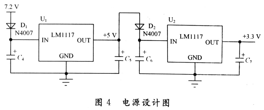
The system's power supply uses a 7.2 V battery, while the C8051F040's high level is 3.3 V, so level shifting is required. This system uses the SMD LM1117 for level conversion. As shown in Figure 4, since the allowable voltage drop of the input and output of the chip is very small, two different levels of LM1117 are used to realize two-level level conversion, and the diode is connected in series in the middle, and the inherent voltage drop of the diode is used to satisfy the chip. Pressure drop requirements.
3 software design
3.1 Wireless module software design The wireless module application sends the motion control signal of the upper computer to the motor control module, and also uploads the motor control quantity of the microprocessor to the upper computer. At the time of reset, the system is initialized and an interrupt is opened. The flag ST is set. After completion, the system enters the sleep mode (ST=00). When the host computer has data acquisition requirements, it communicates with the serial port, which will trigger the system serial port interrupt activation system. Subsequently, the interrupt service routine sets the system to send the command state (ie, ST=01), parses the command signal first, and then packs and sends the command signal. After the transmission is successful, it will enter the wait for receiving data mode (ie, ST=10). Thereafter, if data is sent, the underlying data is uploaded to the application layer, and the data is directly uploaded to the host computer through the serial port to complete a data transmission. The program flow is shown in Figure 5.

3.2 Motor Control Module Software Design The software design flow of this module is shown in Figure 6.
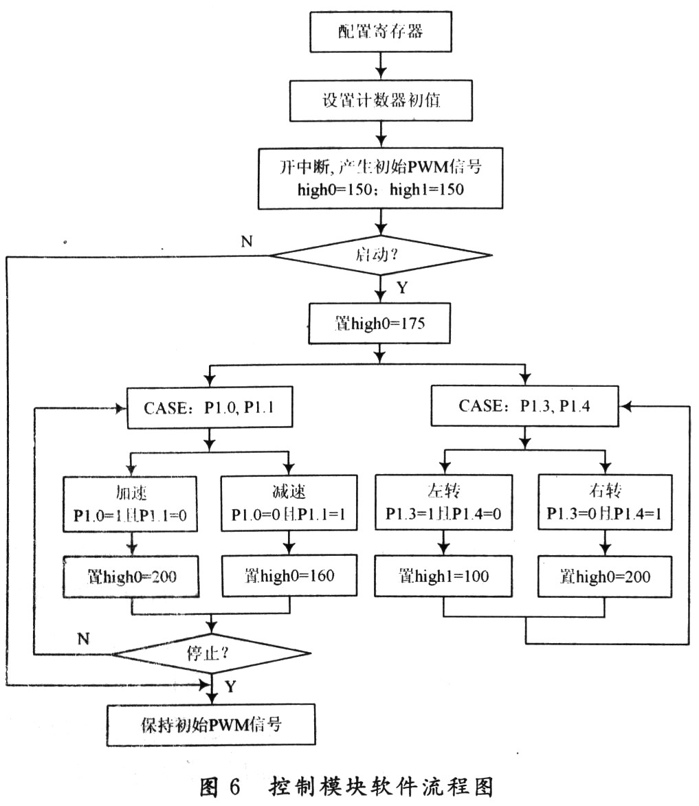
After power-on reset, first complete the initialization of the microcontroller, including watchdog initialization, output port definition, crossbar configuration, configuration clock register, T0 clock controller. The C8051F040 MCU is rich in resources, but based on the 51 core (only 128 special function registers), many of its special function registers cannot be arranged, so the paging mechanism is adopted. Therefore, when configuring different registers, you must first use the paging. The PWM signal is generated by using the interrupt mode in the MCU. The timing unit is set to 0.01 ms, the initial signal is 16 ms, the high time is 1.5 ms, and high0 and high1 respectively control the high level of the speed control waveform and the corner control waveform. time. When the start signal is received, P1.0, P1.1 receive the speed signal, and P1.3, P1.4 receive the corner signal.
4 Conclusion This paper designed a simulation platform with C8051F040 as the control core. Through communication with the host computer, the requirements of robot simulation driving can be well satisfied. The system adopts the way that the upper computer wirelessly controls the physical model, making the simulation driving safer and more reliable. The system has a good expandability. Through wireless communication, more data acquisition systems can be added to feed back information to the host computer, which expands the application range of the platform. If the positioning feedback system is added, the host computer can shield the motion of the physical model for algorithm simulation and experiment. In terms of parameters, a high-precision measurement feedback system can be added to meet higher simulation requirements by maintaining real-time communication with the host computer.
Straps&Wraps&Supports, Yoga Supplies,Wrist Support,Sports Protection
Garage Gym,Cross Training Co., Ltd. , http://www.nbfunctionaltrainer.com