![<?echo $_SERVER['SERVER_NAME'];?>](/template/twentyseventeen/skin/images/header.jpg)
Abstract: In order to achieve the goal of reducing the manufacturing cost (heat sink quality) and speeding up heat dissipation for high-power LED street lamp products, the structure of LED street light radiator is optimized. Based on the parametric modeling and thermal analysis of the original structure, the effects of plate thickness, fin thickness, fin spacing and fin height on the product quality and heat dissipation were analyzed by orthogonal test. The effects of heat conduction and heat convection on heat dissipation under the same structure are studied, and a better optimization result is obtained. The data results show that the improved maximum temperature of the radiator is more than 11 °C lower than the original model, and the quality is reduced by about 15.3%.
At present, LED lighting products are gradually replacing traditional lighting fixtures into mainstream lighting products. For high-power LED street lights, light efficiency is the focus of luminaire designers. However, the low junction temperature of LED modules is the key to achieving long life and high light efficiency. In reality, there are many reports about the early failure of street lamps, called dead lights, which is a huge constraint on public lighting. Therefore, how to reduce the junction temperature of high-power LED products is one of the hot issues.
As we all know, the LED photoelectric conversion efficiency is limited to 15% to 20%, and the rest of the electrical energy is almost completely converted into thermal energy, so when the LED product works, a large amount of heat will be generated. When a plurality of LEDs are densely arranged to form a street light, the heat accumulation effect is more serious. If this heat is not released as quickly as possible, the resulting thermal effects will be very noticeable. This will cause heat accumulation inside the chip, resulting in a series of problems such as drift of the emission wavelength, decreased light extraction efficiency, accelerated aging of the phosphor, and shortened service life.
In this paper, the finite element analysis software ANSYS is used to analyze the LED street lamp, and the heat dissipation structure is designed and optimized to reduce the manufacturing cost and accelerate the heat dissipation.
1 Radiator structure design and modeling
Under normal conditions, there are three ways to transfer heat: conduction, convection, and radiation. Because the radiation heat dissipation is very small, this paper mainly discusses two heat transfer modes, conduction and convection.
In LED street lamps, heat conduction is mainly manifested in the package structure and the heat sink, and the heat convection is mainly reflected by the heat sink. Therefore, in high-power LED street lamps, the structural design of the external heat sink is critical, directly affecting the heat dissipation capability of the entire system.
When manufacturing LED street lamps, the packaged LED light source is usually soldered to the MCPCB, and then the MCPCB and the external heat sink are fixed on the heat sink by using a heat conductive adhesive and a mechanical fastener method, as shown in FIG. The main heat transfer channels are: PN junction - Cu column - MCPCB - radiator - air (environment).
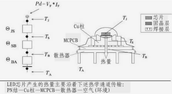
Figure 1 Schematic diagram of the heat transfer channel
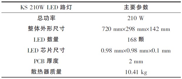
This paper mainly considers the influence of the heat sink on the heat dissipation. The heat sink structure used is a good heat conductor with many heat radiating fins. The MCPCB loaded with the LED light source is fixed by a "heat conducting plate" with a certain thickness. 2, the main parameters are shown in Table 1.
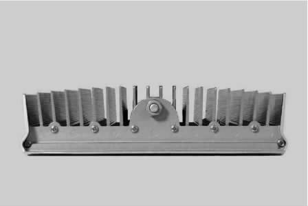
Figure 2 KS street light physical map
Table 1 Basic parameters of street lamps
First, according to the actual size of the luminaire, package light source, etc., the model is established in the finite element simulation analysis software ANSYS as follows.
In this model, considering the main way of heat transfer of the luminaire, the influence of the pins of the packaged light source on heat dissipation is neglected. At the same time, since the thermal conductivity of the epoxy resin for encapsulation is only 0.2 W/mK, it is subjected to a heat treatment here. In addition, it is assumed that each contact surface is an ideal contact interface, that is, the interface thermal resistance is not considered. In the simulation process, the boundary conditions are set as follows: the chip power is 1 W, the photoelectric conversion efficiency is set to 15%, the air convection coefficient is set to 5, the heat sink blackness is 0.5, and the ambient temperature is 25 °C.
2 Radiator parameter optimization
Nowadays, the following problems exist in the design of LED street lamp heat dissipation: the area of ​​the heat dissipating fins is arbitrarily set; the arrangement of the heat dissipating fins is unreasonable; the arrangement of the heat dissipating fins of the lamps does not take into account the use of the lamps, affecting the effect of the fins; Heat conduction, neglect convection heat dissipation; neglect the balance of heat transfer. This often results in a mass of the heat sink, some of which have no function or have limited effect.
2.1 Parameter Optimization Experiment 1
In this paper, the orthogonal test is used to optimize the design of the thickness of the bottom plate, the thickness of the fin, the fin spacing and the fin height. Taking the above four parameters affecting the heat dissipation performance of the heat sink as the factors, each factor takes 4 levels, and the model quality and the highest temperature are used as indicators. The orthogonal table L16 (44) simulation experiment is used, and the results are shown in Table 2.
Table 2 Orthogonal test results table
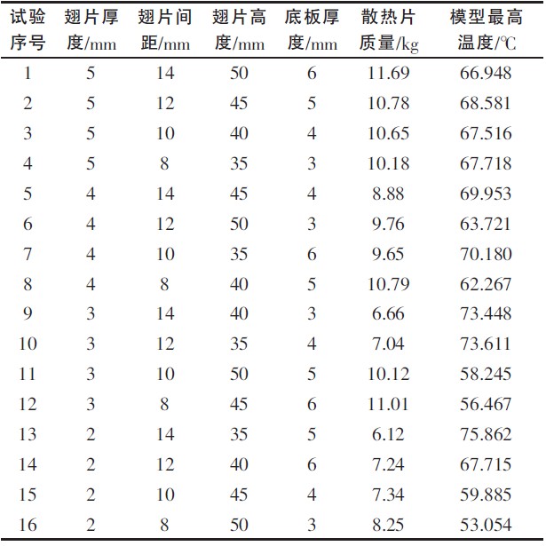
According to the data in the orthogonal test table, the above four factors are used to calculate the extreme difference of the test indicators. The results are shown in Tables 3 to 6. The data in the table shows that the factors affecting the heat sink quality are: fin thickness, fin spacing, fin height, and floor thickness; the factors affecting the highest point temperature of the model are: Fin spacing, fin height, fin thickness, bottom plate thickness.
Table 3 Range analysis of fin thickness versus test index
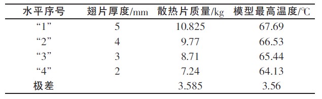
Table 4 Range analysis of fin spacing to test indicators
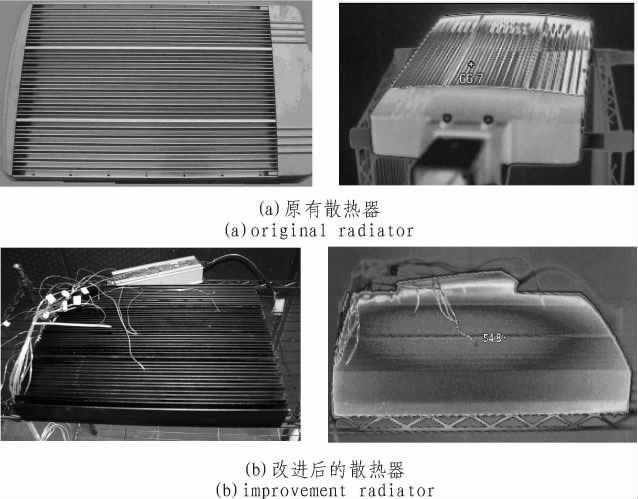
Table 5 Range analysis of fin height to test index
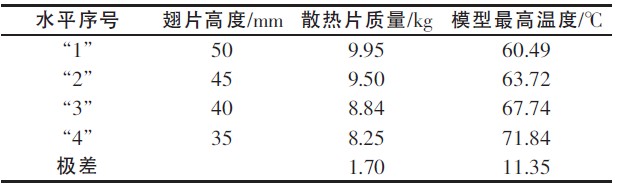
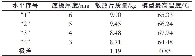
Table 6 Analysis of the range of the thickness of the bottom plate to the test index
From the analysis of the test results, it can be concluded that in order to obtain a better heat dissipation effect when designing a high-power LED finned heat dissipation structure, the fin thickness and the fin pitch should be as small as possible, but in reality these values ​​cannot be infinitely small. . First, since the natural convection reaches a long time for thermal equilibrium, the substrate and tooth thickness of the natural convection heat sink should be sufficient to resist the impact of the instantaneous thermal load. Secondly, the fin pitch is reduced and the number of fins is increased, which causes a decrease in static pressure. If the number of fins is too dense, the air flow rate will be lowered, and the heat dissipation efficiency of the heat sink will be lowered.
In addition, in practice, the overall height of the luminaire is limited due to aesthetics and certain environmental requirements. This defines the height of the heat sink, which is the sum of the height of the bottom plate and the fins. If the thickness of the bottom plate is increased, the height of the heat sink is lowered. In the entire heat dissipation structure, the main function of the bottom plate is to derive the heat generated by the internal light source of the lamp, and then the external fins are dissipated. Therefore, choosing the proper thickness of the substrate and the height of the fins is also an effective way to accelerate heat dissipation.
2.2 Parameter Optimization Experiment 2
In the existing LED street lamp heat dissipation structure, the heat conduction plate method is adopted, that is, the bottom plate of a certain thickness is used as the temperature equalization plate, and the heat source is firstly warmed off; this part mainly plays the role of heat conduction, and the heat generated by the LED is derived from the inside of the lamp. . The heat is then dissipated by external fins. However, the external fin heat dissipation mechanism, that is, the heat dissipation effect is best in which form and proportion, and no further research and optimization of such problems have been found.
In order to illustrate the effect of conduction and convection on heat dissipation, this paper uses ANSYS to analyze the heat dissipation process of a single LED. The total length is constant throughout the test. The overall heat dissipation process is the result of the interaction between heat conduction and convection. In order to explain the respective influences, the fins are divided into a conductive part and a convection part for analysis. In the test, the hypothetical non-conducting portion was refined to increase its convection area. A thermal analysis of the model with a total length of 50 mm under a single LED was performed using ANSYS. The results are shown in Table 7.
Table 7 Table of relationship between temperature and "conduction length"
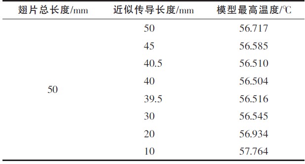
It can be seen from the above results that the longer the "conduction length" is, the lower the temperature is; because the longer the "conduction length", the corresponding convection is not the best, and the two are mutually constrained throughout the heat dissipation process, only in the When both are chosen very reasonably, the best results can be obtained. As the "conduction length" selected in this test is 40 mm, the lowest temperature of 56.504 ° C is obtained, as shown in FIG.
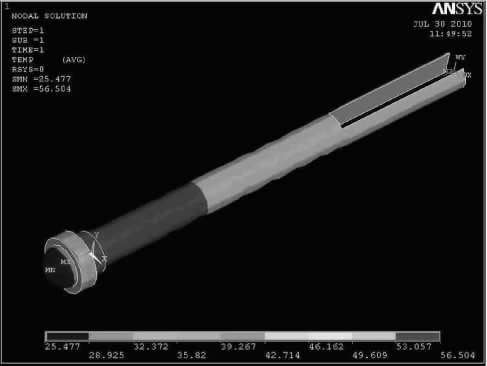
Figure 4 Best "conduction length" temperature profile
2.3 Results verification
Combined with the above test analysis results, after fully considering the appearance of the LED street lamp product, the quality of the heat sink, and emphasizing the balance between heat conduction and convection heat dissipation, the heat sink structure of the LED street lamp product is optimized. It can be seen from Table 8 that the parameter-optimized structure first reduces the mass of the heat sink, and its mass is reduced from 10.41 kg to 8.82 kg, which is 15.3% lower than the original one. Fig. 5 is a structural view before the heat sink is improved.
Table 8 Comparison table before and after improved structure
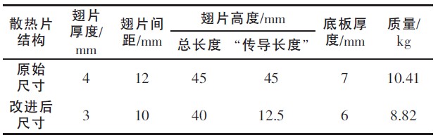
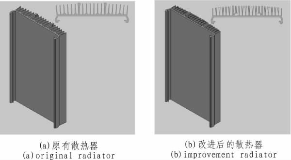
Figure 5 heat sink structure
The thermal analysis and actual measurement of the two products were carried out by ANSYS analysis software and infrared thermal imager. The results are shown in Figure 6 and Figure 7, respectively.
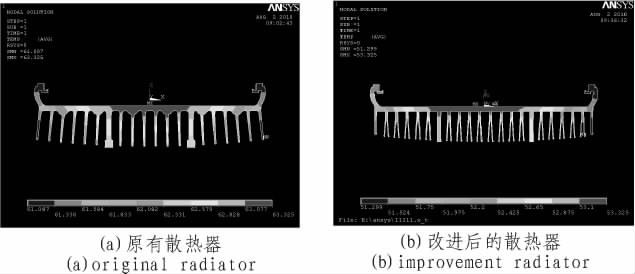
Figure 6 ANSYS thermal analysis temperature field distribution map
Figure 7 Radiator physical and infrared measured map
As can be seen from the above figure, using ANSYS analysis, the temperature dropped from 63.325 ° C to 53.325 ° C, a decrease of 10 ° C; and the measured temperature decreased from 66.7 ° C to 54.8 ° C. The drop was 11.9 °C. The temperature distribution in the simulation results is basically consistent with the measured temperature distribution, and the temperature range is slightly smaller than the measured temperature range. This is mainly due to the neglect of the interface thermal resistance, the thermal resistance of the chip and the shell bonding material, and the MCPCB and the heat sink during the simulation. The thermal resistance of the bonding material.
3 Conclusion
For a street lamp composed of a plurality of high-power LEDs densely arranged, more heat needs to be effectively dissipated from the chip junction region, so the thermal management problem of the high-power LED street lamp is a challenge for the LED heat dissipation technology.
Firstly, based on the existing LED street lamp products, a finite element model based on thermal conduction/thermal convection is established. The thermal analysis of the heat dissipation structure is carried out by ANSYS. In addition, the quality and heat distribution of different structural parameters are analyzed through two optimization experiments. The influence of heat conduction and heat convection on heat dissipation is also studied. Finally, an ideal optimization result is obtained. The optimized structure has been simulated by software and the measured results show that the quality of the improved radiator is reduced by about 15.3% compared with the original radiator. At the same time, the temperature is much lower than the original model, and the drop is over 11 °C; The design of the radiator in the future provides a guiding direction.
Our latest USB Type-C socket offers optional splash protection (IPX4 level) and valuable circuit board design space.
Our latest USB Type-C socket protects equipment in harsh environments. It has the industry-leading IPX8 waterproof performance and meets the IEC60529 standard.
Waterproof USB Connector
ShenZhen Antenk Electronics Co,Ltd , https://www.antenk.com