![<?echo $_SERVER['SERVER_NAME'];?>](/template/twentyseventeen/skin/images/header.jpg)
With the rise of intelligent terminals and the enrichment of wireless data application services, the number of data users in wireless communication systems has increased substantially, and the data content is no longer limited to traditional text or images. In the future, users will have multimedia services such as high-definition video and mobile TV. The increasing demand for wireless networks has led to an explosive growth in wireless network traffic. According to market organizations, in the next 10 years, wireless data services will grow by 500 to 1000 times, with an average annual increase of 1.6 to 2 times, which puts higher demands on the network capacity of wireless communication systems.
There are various ways to improve the network capacity of a wireless communication system, including: improving spectrum efficiency, increasing network density, increasing system bandwidth, and intelligent service offloading. In recent research, the method of improving spectrum efficiency based on large-scale antenna array technology has attracted more and more researchers' attention and is an important technology in future mobile communication systems.
The basic feature of a large-scale antenna array system is that it can obtain more accurate beam steering capability than a conventional antenna array system (no more than eight antenna arrays) by arranging a large number of antenna arrays (from tens to thousands) on the base station side. Then, through spatial multiplexing technology, more users are simultaneously served on the same time-frequency resource to improve the spectrum efficiency of the wireless communication system, thereby meeting the transmission requirements of massive information in the future B4G/5G wireless communication system. In addition, the large-scale antenna array system can also well suppress the interference in the wireless communication system, and bring about huge interference suppression gains within the cell and between cells, so that the capacity and coverage of the entire wireless communication system are further improved.
However, when deploying a large-scale antenna array system in a wireless channel environment where there is no mutuality between the uplink and downlink, the biggest problem encountered is the downlink pilot overhead problem.
The downlink pilot overhead is proportional to the number of antennas, and the terminal needs to feed back the downlink channel state information to the base station, which also brings a relatively large feedback overhead, which seriously affects the performance of the large-scale antenna array system.
Compressed sensing is when the signal is acquired (analog to digital), and the meaning of signal compression is completed. Since the rigorous mathematical results or theories related to compressed sensing have just emerged, compressed sensing is a fairly new field and a very hot research front in recent years, and has been widely concerned in several application fields.
Through analysis, the wireless channel is sparse in the time domain, and is embodied as multipath with different delays and different powers. Similarly, due to the channel correlation between antennas, after a certain transformation, it should be sparse in the transform domain. This makes it possible to use compressed sensing techniques to reduce pilot overhead.
This paper mainly introduces the technical principle of compressed sensing and analyzes its application in wireless communication systems based on large-scale antenna array technology in the future.
1 Technical principle
In digital signal processing, the conversion process from analog signal to digital signal generally takes place. Sampling and quantization are prerequisites for signal processing.
The sampling theorem was first proposed by American telecommunications engineer Nyquist in 1928 and is called the Nyquist sampling theorem. The theorem states that the original signal should be recovered from the discrete sampled signal without distortion, and the sampling rate should be low. Double the bandwidth of the original signal. This theory almost dominates the process of acquiring, processing, storing, and transmitting all signals.
D. Donoho, E.Candes, and Chinese-American scientist T.Tao et al. conducted a lot of in-depth research on signal sparseness and approximation theory. In 2004, a new information acquisition guidance theory was proposed: Compressed Sensing Theory. The theory of compressed sensing states that the compressible (sparse) signal can still accurately recover the original signal after being sampled at a much lower sampling rate than the Nyquist sampling rate.
Compressed sensing breaks through the limitations of the Nyquist sampling theorem, making information theory a new stage of research. The basic idea is that as long as the signal is compressible or sparse in a certain transform domain, then a The transform-base uncorrelated observation matrix projects the transformed high-dimensional signal onto a low-dimensional space, and then reconstructs the original signal from these small projections (or measured values) with high probability by solving an optimization problem. .
In the framework of compressed sensing theory, the sampling rate is not determined by the bandwidth of the original signal, but depends on the structure and content of important information in the signal. The measured value is not the signal itself, but the projection value from high dimension to low dimension. Each measurement contains a small amount of information for all sample signals, and the number of measurements required to recover the signal is much less than the number required by the sampling theorem.
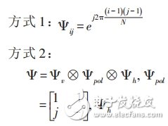
For an N*1 dimensional signal s, where s contains K non-zero elements, the signal s is transformed by the formula (1) to obtain an N*1 dimensional variable x, and then the M*1 dimensional measurement signal y is obtained by the formula (2). The purpose of compressed sensing is to reconstruct the signal s by measuring the signal y.
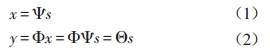
Where Ψ is an N*N-dimensional sparse transformation matrix, Φ is an M*N-dimensional measurement matrix (also called a projection matrix or a random sampling matrix), and the design of Ψ and Φ seriously affects the performance of the compressed sensing technology, K “M†The value of N and M satisfies the formula (3).
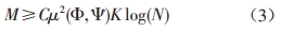
Among them, μ2 (Φ, Ψ) represents the correlation between the matrix Ψ and Φ.
Signal reconstruction is the core of compressed sensing technology. It is a process to find the most sparse solution s under the condition of obtaining observation value y. Here we need to introduce the norm concept in matrix theory to describe the signal reconstruction problem of compressed sensing theory.
The P-norm of the definition vector Z={z1,z2,...,zN} is:
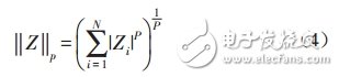
When p=0, the 0-norm of the vector Z is obtained, indicating the number of non-zero elements in Z.
In general, for a non-sparse signal x in the case of s after thinning transformation, the signal recovery problem in the compressed sensing theory is transformed into the minimum 0-norm problem under linear constraints, which can be used in equation (5). expression:
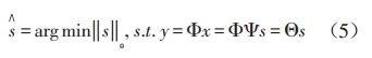
The optimization problem of the above 0-norm is a non-convex optimization problem, that is, it cannot be solved in the polynomial, and it is not able to verify the validity of the solution, so it needs to be converted into other norms, such as 1-norm or 2-norm. The number, the study proves that for the minimum 0-norm problem of the formula (5), a solution equivalent to the 0-norm can be obtained by solving a simpler 1-norm optimization problem. Therefore, the theory of compressed sensing is usually described by equation (6):
The solution to formula (6) can be implemented by optimization theory such as linear programming algorithm, and other fast optimization algorithms can be used in actual implementation.
2 Application analysis
Compressed sensing application features include:
(1) The observed signal is not sparse, such as an OFDM system frequency domain channel response or a linear array response.
(2) By transforming the base coordinates of the observed signal, the signal becomes sparse under another set of substrates. For example, the frequency domain channel response is sparse in the time domain after DFT transform.
(3) Sparseness (sparse location) has the characteristics of agnostic and variability, which is a necessary condition for applying compressed sensing if the sparse position has susceptibility or constancy.
Field tests show that most wireless channels are generally multipath sparse in the time domain. According to the compressed sensing theory, this sparsity means that the user's proprietary pilot overhead can be greatly reduced.
In addition, as the number of antennas on the base station side increases, the wireless channel also exhibits sparsity in the airspace, which means that the cost of the public pilot of the cell can be effectively reduced by the compressed sensing technology.
2.1 User-specific pilot design
According to the theory of compressed sensing, according to formula (6), the time-domain wireless channel coefficients with sparsity can be recovered by the compressed sensing technology by a small amount of pilot observation signals distributed in the frequency domain.
In the user-specific pilot design of future mobile communication systems, based on the compressed sensing technology, the issues to be considered are:
(1) Number of pilots: Estimate the sparsity K of the channel, and then use equation (3) to roughly calculate the number m of pilot symbols required.
(2) Pilot position: determined by the measurement matrix. The randomness must be guaranteed during design. The cell identifier, frame number, sub-frame number, and resource location can be used as the random matrix generation factor to obtain a sufficiently sparse pilot position, or Pre-defining a number of sets of random pilot positions during normalization, and determining which set of random pilot positions to use according to system parameters during scheduling, which is significantly different from existing LTE systems, in which pilots are evenly distributed, The interval mainly considers the relevant bandwidth.
(3) Transformation matrix: The discrete Fourier transform matrix is ​​prioritized.
(4) Signal reconstruction: The receiver recovers the time domain channel h by using a small number of frequency domain pilot channel values ​​y according to the flow shown in FIG. 1, wherein the target function optimization can use the Stomp algorithm with lower complexity.
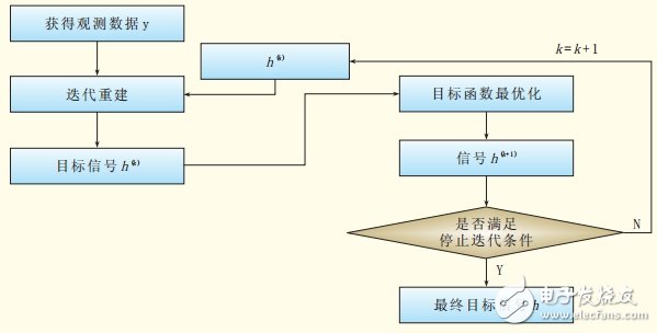
Figure 1 Signal reconstruction process of compressed sensing technology
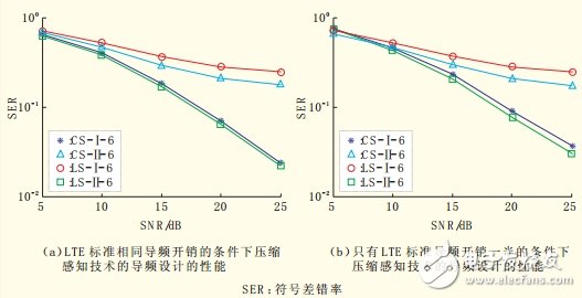
Figure 2 Simulation performance of pilot design based on compressed sensing technology
Figure 2 shows the performance of the user-specific pilot design based on the compressed sensing technology compared with the traditional LTE pilot. Figure 2 shows the symbol error rate in the extended urban environmental channel model (ETU) scenario, 10MHz, 16QAM. (SER) comparison, where LS-I-6 stands for LTE standard pilot mode, time domain does not perform CP-based truncation processing, subcarrier spacing is 6 simulation results under simulation parameter setting; LS-Î -6 stands for LTE standard Pilot mode, CP-based truncation processing in the time domain, simulation results under the simulation parameter setting of subcarrier spacing of 6; CS-I-6 represents the compressed sensing pilot mode, and the time domain is not subjected to CP-based truncation processing, sub- The simulation result under the simulation parameter setting with the same carrier overhead and LTE pilot overhead; CS-Î -6 stands for compressed sensing pilot mode, CP-based truncation processing in time domain, and the same sub-carrier overhead and LTE pilot overhead simulation parameters The simulation result is set; CS-I-12 stands for compressed sensing pilot mode, the time domain does not perform CP-based truncation processing, and the subcarrier overhead is the simulation result under the simulation parameter setting of half of LTE pilot overhead; CS-Î - 12 represents compressed sensing Pilot pattern, processing the time-domain truncated CP made based LTE overhead subcarriers pilot overhead simulation results in half of the simulation parameters. Figure 2(a) shows the performance of the pilot design of the compressed sensing technology under the same pilot overhead of the LTE standard, and Figure 2(b) shows the compressed sensing technique with only half of the pilot overhead of the LTE standard. The performance of the pilot design. It can be seen from the simulation results that the pilot designed based on the compressed sensing technology can effectively reduce the system overhead and improve the decoding capability of the receiver.
2.2 Community public pilot design
In a large-scale antenna array system, the number of antennas on the base station side increases, which increases the public pilot overhead of the cell, which seriously affects the performance of future mobile communication systems. Therefore, a channel estimation method based on low pilot density is sought. Very necessary.
As the number of antennas on the base station side increases, whether or not the channel is sparse in the airspace is a problem that needs to be verified first.
Figure 3 shows the angular domain power spectrum distribution obtained by performing discrete Fourier transform (DFT) on the instantaneous channel formed by the base station with 128 antennas. It can be seen that the variables obtained after the transformation are sparse, so Compressed sensing technology designs the public pilot of the cell in the future mobile communication system.
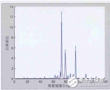
Figure 3 Angle domain power spectrum distribution of 128 antenna channels
The number of pilots for small-area public pilot design, pilot position, and signal reconstruction can refer to the idea of ​​user-specific pilot design. There are two ways to transform matrix design:

In the formula, Ψ is a DFT matrix.
The simulation results of the inter-cell public pilot design based on Mode 1 and Mode 2 are shown in FIG. 4 . Figure 4 shows the cumulative distribution function, regardless of interference/noise.
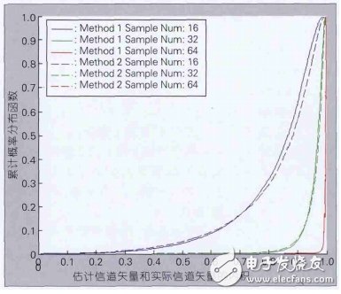
Fig.4 Analysis of spatial sensing compression performance of different transform matrices
It can be seen that the two methods can reconstruct the spatial channel better through the compression sensing technology. When the number of random sampling points is relatively large, the performance difference between the two transformation matrices when reconstructing the channel is not large, but when the number of random sampling points is relatively small, mode 2 The channel can be better reconstructed, mainly because the transform matrix provided by mode 2 better reflects the correlation between the antennas.
3 Conclusion
Through theoretical analysis and a large number of simulations, it is proved that the compressed sensing technology can effectively reduce the system pilot overhead and improve system performance.
Subsequent consideration may also be given to combining the compressed sensing technology with the cognitive radio technology that may be used in future mobile communication systems to discover idle resources in a frequency band with a relatively large amount of idle spectrum, thereby effectively reducing the system hardware implementation cost, or compressing sensing technology. Combined with other antenna dimensionality reduction technologies to enhance the user experience of future mobile communication systems.
Coffee And Spice Grinder,Manual Spice Grinder,Electric Salt And Pepper Grinders ,One Handed Pepper Grinder
JIANGMEN JIANGHAI DISTRICT SHENGHUI ELECTRIC CO.,LTD , https://www.shenghuielectric.com