![<?echo $_SERVER['SERVER_NAME'];?>](/template/twentyseventeen/skin/images/header.jpg)
In the circuit design, the role of the full bridge is very important. When the four diodes in the bridge rectifier circuit are packaged together, they form a full bridge circuit, and the full bridge circuit is actually the H bridge circuit we often say. This article will mainly introduce the working principle of H-bridge motor drive, and carry out comprehensive analysis from two aspects, counterclockwise and clockwise.
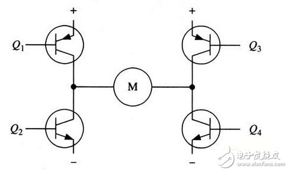
Figure 1 H-bridge motor drive circuit
A typical DC motor control circuit is shown in Figure 1. The circuit takes its name from the "H-bridge drive circuit" because its shape resembles the letter H. The four triodes make up the four vertical legs of H, and the motor is the horizontal bar in H (Note: Figure 1 and the subsequent two figures are just schematic diagrams, not a complete circuit diagram, where the triode's drive circuit is not drawn.
As shown in the figure above, the H-bridge motor drive circuit includes four triodes and one motor. To operate the motor, a pair of transistors on the diagonal must be turned on. Depending on the conduction of the different pairs of transistors, current may flow through the motor from left to right or from right to left, thereby controlling the steering of the motor.
To operate the motor, a pair of transistors on the diagonal must be turned on. For example, as shown in Figure 2, when the Q1 tube and the Q4 tube are turned on, the current passes from the positive pole of the power supply through the Q1 from left to right through the motor, and then back to the negative pole of the power supply via Q4. As indicated by the current arrow in the figure, the current in the flow direction will drive the motor to rotate clockwise.
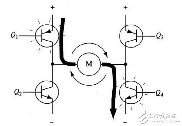
Figure 2 H-bridge circuit drive motor rotates clockwise
When transistors Q1 and Q4 are turned on, current will flow from left to right through the motor, causing the drive motor to rotate in a particular direction (the arrow around the motor indicates a clockwise direction).
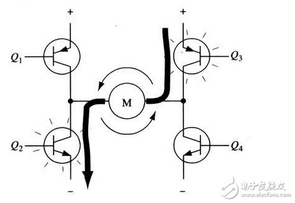
Figure 3 H-bridge circuit drive motor rotates counterclockwise
Figure 3 shows the other pair of transistors Q2 and Q3 conducting, current flowing from right to left through the motor.
When transistors Q2 and Q3 are turned on, current will flow from right to left through the motor, causing the motor to rotate in the other direction (arrows around the motor are shown as counterclockwise).
Enable control and direction logic
When driving the motor, it is important to ensure that the two transistors on the same side of the H-bridge are not turned on at the same time. If the transistors Q1 and Q2 are turned on at the same time, the current will flow directly from the positive electrode through the two transistors to the negative electrode. At this point, there is no load other than the triode in the circuit, so the current on the circuit can reach a maximum (this current is only limited by the power supply performance), and even burn out the triode.
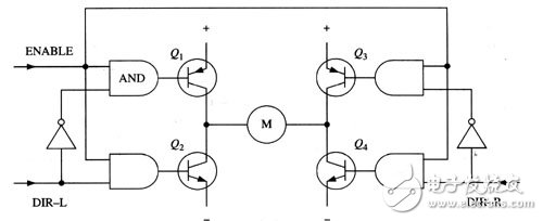
Figure 4 H-bridge circuit with enable control and direction logic
For the above reasons, it is common to use a hardware circuit to conveniently control the switching of the triode in an actual driving circuit. Figure 4 shows an improved circuit based on this consideration. It adds four AND gates and two NOT gates to the basic H-bridge circuit. The four "enable" turn-on signals are connected to the gate so that the switch of the entire circuit can be controlled with this signal. The two non-gates can ensure that only one transistor can be turned on at the same leg of the H-bridge at any time by providing a direction of input. (As in the previous diagram, Figure 4 is not a complete circuit diagram. In particular, the direct connection to the gate and the triode does not work properly.)
With the above method, the operation of the motor only needs to be controlled by three signals: two direction signals and one enable signal. If the DIR-L signal is 0, the DIR-R signal is 1, and the enable signal is 1, then the transistors Q1 and Q4 are turned on, and the current flows from left to right through the motor (as shown in Figure 5); if DIR-L The signal changes to 1, and the DIR-R signal becomes 0, then Q2 and Q3 will turn on and current will flow through the motor in the opposite direction.
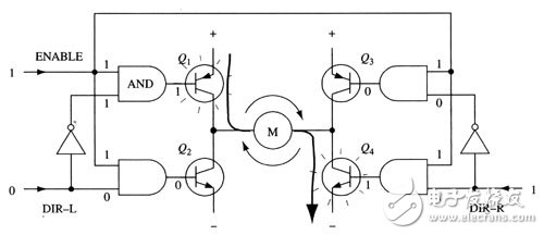
Figure 5: Use of enable and direction signals
In actual use, it is very troublesome to make H-bridge type with discrete parts. Fortunately, there are many packaged H-bridge integrated circuits on the market, and the power supply, motor and control signals can be used at the rated voltage and The use of current is very convenient and reliable. For example, commonly used L293D, L298N, TA7257P, SN754410 and so on.
The H-bridge circuit is often used in inverter circuits and DC motor circuits. Here we only explain the application principle of the H-bridge circuit in DC motors. I hope that you can fully grasp the basic knowledge of the full bridge circuit, which will not only facilitate the rapid design and help us to consolidate the basic knowledge.
This type PLC Splitter devided from Material.Because this ABS BOX PLC Splitter material is ABS BOX,so we call it ABS BOX PLC Splitter.
We have including 1:4,1:8,1:16,1:32,1:64 this 5 models splitter in the group.The main function of this 5 models are the same ,the only difference just for the fiber cable numbers.It is optional for customers.Customers can choose the one the are needed in their network applications.
Warmly welcome customers all over the world to contact us for more products details.
Abs Box Plc,Abs Box type Plc Splitter,Plc Splitter,Passive Optical Network, Optical Splitter
Shenzhen GL-COM Technology CO.,LTD. , https://www.szglcom.com