![<?echo $_SERVER['SERVER_NAME'];?>](/template/twentyseventeen/skin/images/header.jpg)
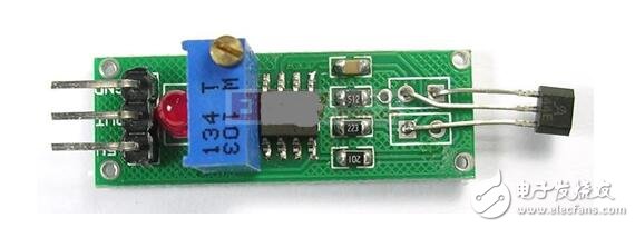
Hall switch, also known as Hall digital circuit, is a new type of electrical accessories, including reverse voltage protector, precision voltage regulator, Hall voltage generator, differential amplifier, Schmitt trigger, temperature The compensator and the complementary collector open-circuit output device are composed of seven parts, featuring non-contact, low power consumption, long service life and high response frequency. The internal use of epoxy resin is sealed and integrated into various harsh environments. Reliable work. The circuit is the ideal device for brushless fans due to its load capacity of up to 400 mA and its complementary output.
The Hall effect is that when a metal or semiconductor chip with current is placed vertically in a magnetic field, a potential difference occurs at both ends of the sheet, and the potential difference at both ends is called the Hall potential U. Its expression is:
U=KIB/d
Where K is the Hall coefficient, I is the current passing through the sheet, B is the magnetic induction of the applied magnetic field, and d is the thickness of the sheet.
The Hall switch is an active magnetoelectric conversion device. It is based on the Hall effect principle and is fabricated by an integrated package and assembly process. It can easily convert the magnetic input signal into an electrical signal in practical applications. It can also meet the requirements of easy operation and reliability in practical applications in industrial applications.
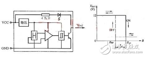
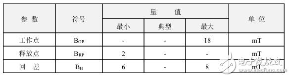
Under the action of the external magnetic field, when the magnetic induction exceeds the conduction threshold BOP, the Hall circuit output tube is turned on and outputs a low level. After B increases again, the circuit remains in the on state. If the B value of the applied magnetic field is reduced to BRP, the output tube is turned off and the output is high. We call BOP the working point, BRP as the release point, and BOP-BRP=BH as the return difference. The presence of a backlash enhances the anti-jamming capability of the switching circuit.
The Hall switch circuit consists of a reverse voltage protector, a precision voltage regulator, a Hall voltage generator, a differential amplifier, a Schmitt trigger, a temperature compensator, and a complementary open collector. Below we briefly introduce the functions of each part.
Voltage regulator: When the power supply voltage changes from 3.5V to 20V, the circuit is guaranteed to work normally.
Reverse protector: when the application power is reversed or interfered by the reverse pulse voltage during use, the circuit is protected, and the protection voltage can reach 30V;
Hall voltage generator: converts a varying magnetic signal into a corresponding electrical signal.
Differential Amplifier: Amplifies the weak voltage signal from the Hall voltage generator output.
Schmitt Trigger: Converts the analog signal output from the differential amplifier into a digital signal.
Temperature Compensator: Ensures that the integrated circuit operates reliably between -20 ° C and +85 ° C.
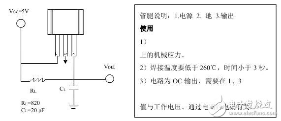
Complementary output: The output current directly drives the two sets of windings of the brushless fan.
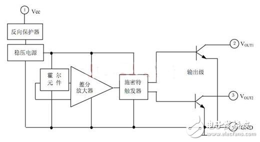
As can be seen from the above figure, when the brushless fan is powered on, if the Hall voltage generator is subjected to the alternating magnetic field, the potential states of the output terminals 2 and 3 also change, thereby changing the direction of the load current, so that the fan Normal operation.
Fourth, Hall switch - classification1, unipolar Hall effect switch (digital output)
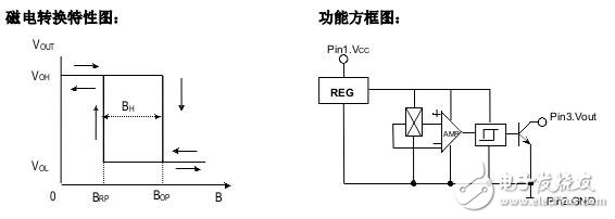
The unipolar Hall effect switch has a magnetic operating threshold (Bop). If the Hall cell is subjected to a flux density greater than the operating threshold, the output transistor will turn on; when the flux density drops below the operating threshold (Brp), the transistor will turn off. Hysteresis (Bhys) is the difference between two thresholds (Bop-Brp). This built-in hysteresis page enables a net switching of the output even in the presence of external mechanical and electrical noise. The digital output of the unipolar Hall effect can be adapted to a variety of logic systems. These devices are ideal for use with simple magnetic bars or magnets. The unipolar Hall switch will have a magnetic pole induction for each of its front and back sides. In the specific application, attention should be paid to the magnetic pole of the magnet, and the unipolar non-inductive output will be caused.
2, bipolar Hall effect switch (digital output)
The bipolar Hall is specifically divided into a bipolar non-latching Hall switch and a bipolar latch type Hall switch.
Bipolar Hall-effect switches are normally turned on with sufficient magnetic field strength in the South Pole and are turned off with sufficient magnetic field strength in the North Pole, but if the magnetic field is removed, it is randomly output, either open or closed. A bipolar latched Hall-effect switch is normally turned on with sufficient south pole magnetic field strength and is turned off if the north magnetic field strength is sufficient, but does not change the output state if the magnetic field is removed. These Hall-effect switches can be magnetically driven using north-south alternating magnetic fields and multipole ring magnets.
3. Bipolar latch type Hall effect switch (digital output)
When it is placed on the n pole (or s pole), it will remain on after the magnetic field is removed; it will only be turned off when it is placed on the s pole (or n pole), and it will remain on or off after the magnetic field is removed. Until the next time the magnetic field changes. This feature of retaining the last state is the latching feature. This type of Hall benefit switch is a bipolar latching Hall effect switch.
4, all-pole Hall effect switch (digital output)
Unlike other Hall-effect switches, these devices can be turned on as long as there is a strong enough north or south pole magnetic field; in the absence of a magnetic field, the output turns off.
5, linear Hall effect sensor IC (analog output)
The voltage output of the linear Hall-effect sensor IC accurately tracks changes in flux density. In the static (no magnetic field), in theory, the output should be equal to half of the supply voltage in the operating voltage and operating temperature range. Increasing the South Pole magnetic field will increase the voltage from its quiescent voltage. Conversely, increasing the north magnetic field will increase the voltage from its quiescent voltage. These components measure the angle, proximity, motion and magnetic flux of the current. They are capable of reflecting mechanical events in a magnetically driven manner.
6, micro power type Hall effect switch (digital output)
With the popularity of portable devices such as mobile phones, notebook computers, and DVs, the power consumption of Hall ICs has been demanded, resulting in a new class of Hall ICs. It is a class of digital Hall ICs that are separately separated by power consumption. The internal sleep mode is used to reduce power consumption, and the average power consumption can reach uA level. It can also be divided into single-stage Hall IC, locked-type Hall IC, and full-level Hall IC according to functions. This type of system is generally used for long-term battery power supply.
Five, Hall switch - failure identificationTo give you a simple method: Hall facing yourself (seal face), the pin is down, from left to right: positive (switch Hall 4.5V to 24V, linear Hall 5V), negative, and sputum ( Signal), connected to the positive and output resistors (1 to 10K). Indirect LED and indirect output of a light-emitting diode (or a multimeter to measure voltage, high level equal to the power supply voltage low level is equal to zero). After the power is turned on, use the magnet to move closer to or away from the Hall to see if the LED changes in illumination. If there is a change, it will be good. If it is not changed, it will be bad.
Sixth, Hall switch - single pole switching circuit (OH137)The Hall switch is divided into a single-pole switch and a bipolar switch. The OH137 is a single-pole switch. The two-pole switch can be queried on the Internet under OH413, OH41, etc. as a reference computer. Please see the following for details.
The OH137 Hall Switch circuit is a series of products developed and manufactured for the customer's low cost and high performance requirements. It has a wide range of applications and reliable performance. The circuit consists of a reverse voltage protector, voltage regulator, Hall voltage generator, differential amplifier, Schmitt trigger and open collector output stage, which can convert the changing magnetic field signal into digital voltage output.
Typical application areas: DC brushless motors, household appliances, sewing equipment, textile machinery, encoders, security alarms and other automation control areas.
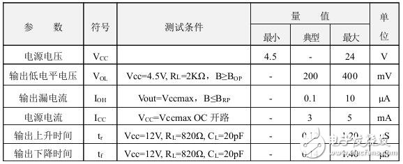
Limit parameters: (TA=25°C)
Power supply voltage VCC·································
Output load current IO···················25mA
Operating temperature range TA ················-40~85°C
Storage temperature range TS ·················-55~150°C
Magnetic characteristics: (VCC=4.5~24V) 1mT=10GS
Test circuit
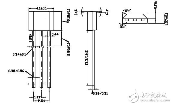
Dimensional drawing:
The basic uses of the Hall switch integrated sensor include the following areas: ignition system, security system, speed, mileage measurement, limit switches for mechanical equipment, push button switches, current measurement and control, position and angle detection, and more.
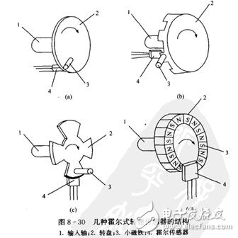
(1) Hall type speed sensor. Figures 8-30 illustrate the construction of several Hall-type speed sensors.
(2) Hall counting device. Figure 8-31 shows a schematic diagram of the operation of the device for counting the balls by the Hall sensor and a circuit diagram.
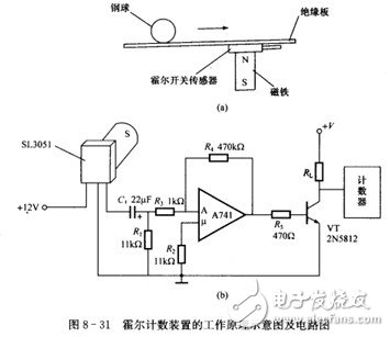
Because the steel ball is a ferromagnetic object, the long-term magnet is fixed in the device. When the steel ball rolls over, the magnetic field changes once, and the Hall voltage of the sensor output also changes once, which is equivalent to the discovery of a pulse. The signal is amplified by an operational amplifier. The base of the triode is sent, and the triode is turned on once. A counter is connected to the collector of the triode to count the rolled steel balls.
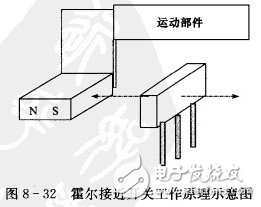
(3) Hall proximity switch (Figure 8-32). The moving part is provided with a permanent magnet whose axis is in line with the axis of the sensor. When the magnet moves with the moving part to a few millimeters to ten millimeters from the sensor (determined by design), the output of the sensor changes from a high level to a low level, and the relay circuit is pulled or released by the driving circuit, and the moving part is stopped.
This Automation curtain is specially designed for automation industry. SDKELI LSC2 light curtain is designed for automation field, with small size, compact structure and strong anti-interference ability, and the product meets IEC 61496-2 standards. The automatic light curtain is with reliable quality and very competitive price. It has been used in many factories and has replaced curtains from Sick, Omron, Banner, Keyence, etc.
Automatic Light Curtain,Laser Light Curtain,Automation Light Beam Sensor,Automatic Infrared Beam Sensor,Infrared Beam Curttain Sensor,Infrared Beam Sensor
Jining KeLi Photoelectronic Industrial Co.,Ltd , https://www.sdkelien.com