![<?echo $_SERVER['SERVER_NAME'];?>](/template/twentyseventeen/skin/images/header.jpg)
One of the most interesting features when using motors in automotive transmission applications is that they can also be used as generators to charge the car's battery while braking. Roboteq's motor controllers can be fully programmed to take advantage of this feature to achieve regenerative braking in a controlled and progressive manner.
This article discusses the principles behind the simple and very efficient technique of using motor speed detection and introduces a practical example of using a brushless motor connected to a Roboteq controller.
Both electric motor and generator
A simplified model of the motor is a resistor in series with an inductor and a voltage generator. Resistance and inductance are the resistance and inductance of the electromagnetic components inside the motor. The voltage generator represents the voltage generated by the motor itself when the motor is rotating. It is generally called the back electromotive force. The abbreviation is BEMF. The BEMF voltage is a fixed voltage-to-speed ratio (V/RPM).
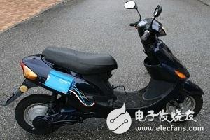
An experimental electric scooter capable of progressive regenerative braking using the Roboteq brushless motor controller.
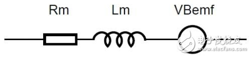
Figure 1: Motor model.
When powering the motor in the mechanically locked state, the model can actually be simplified as a resistor connected to the battery at both ends. The measured current value is I=VBat/Rm. The inductance only affects the voltage plus the instantaneous current, if the voltage The effect of keeping it constant will disappear.
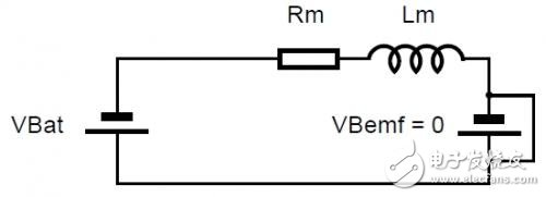
Figure 2: Equivalent circuit when the motor is stopped.
If the motor allows rotation, it will produce a BEMF voltage proportional to the speed of rotation. The model at this time is a resistor plus a generator located at each end of the resistor. The final voltage across the resistor is equal to the battery voltage minus BEMF, and the current is I = (VBat - VBemf) / Rm. In practical applications, this means that as the motor speed increases, the current decreases.
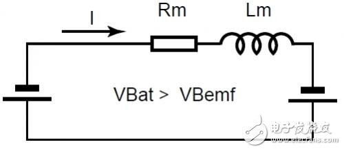
Figure 3: Acceleration status.
If the motor speed can be fast enough to BEMF equals the battery voltage, the two voltage sources will cancel each other out, and the equivalent voltage on the resistor is zero, at which point the battery will have no current flowing out. This is not the case in practical applications because it means that the motor does not have a bit of torque, and always requires a certain amount of torque to overcome the friction.
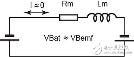
Figure 4: Stable speed without load or friction.
In practical applications, the motor speed will tend to stabilize when the BEMF reaches the torque generating battery current sufficient to overcome the friction and mechanical load of the motor.
However, if the motor is driven by an external force (for example, a car going downhill), the rotation will cause the actual BEMF to equal VBat, and there will be no current flow. If the motor rotates at a faster speed, the BEMF will become larger than the battery voltage, and we will see current flowing from the motor to the battery, at which point the system is in a regenerative (regeneration) state.
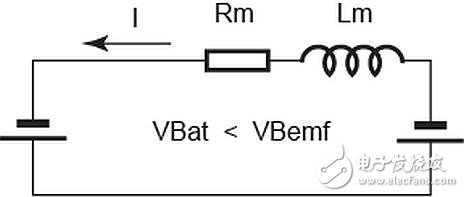
Figure 5: Regenerative braking state.
PWM switching voltage source effect
So far we have assumed that a fixed voltage battery is directly connected to the motor. From this we can see that under constant load conditions, the speed can be controlled by changing the battery voltage.
In modern controllers, changing the voltage is achieved by using a power MOSFET transistor in a half-bridge (unidirectional) or full-bridge (bidirectional) configuration and switching the motor supply at a very fast speed of nearly 20 kHz. This bridge has a bottom MOSFET and a top switch that operate in a complementary manner (the top is turned off when the bottom is turned on and the top is turned on when the bottom is turned off).
When combined with the inductance of the motor, this switch causes the controller to behave like an adjustable voltage source with a value proportional to the on/off duty cycle of the switch. For example, when half of the time is turned on for half of the time, the circuit is equivalent to a generator with half the battery voltage.
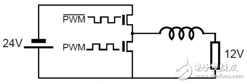
Figure 6: Step-down conversion of 50% PWM.
This effect is also true in the opposite direction. If the battery is not connected and the motor is driven to generate voltage, the PWM switch and motor inductance will double the voltage as a booster at 50% PWM. This boosting effect is a good explanation of how the regeneration occurs when the motor speed is slow and the BEMF is less than the battery voltage.
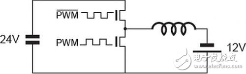
Figure 7: Step-up conversion at 50% PWM.
Vertical Mount D-Sub Connectors
Antenk Standard D-Sub Series Including:
Standard Straight D-Sub Connectors Stamped Contacts
Standard High Profile D-Sub Machined Contacts
Standard Wire Wrap D-Sub Connectors Machined Contacts
Standard Straight D-Sub Connectors Machined Contacts
Standard Dip Solder D-Sub Connector Straight Machined Economy
Standard Density Vertical Low Profile D-Sub Connectors
Standard Density Press Fit D-Sub Connectors
Antenk's Vertical D-Sub Connectors Options
Number of Rows
Shell Size
Mounting Style
Packaging
Gender
Shell
Features of Antenk's Vertical D-Sub Standard Connectors
Available in 5 industry sizes/positions
Standard Density (9 pin, 15 pin, 25 pin, 37 pin, 50 pin).
Low cost & high performance, non-removable stamped contacts.
Nickel shells have indents to provide grounding and additional retention.
Optional mounting d-sub hardware available.
Materials of Antenk's Vertical D-Sub Standard Connectors
Shell: Steel, nickel plated
Insulator: Glass-filled thermoplastic. U.L. rated 94V-O
(260°C process temp)
Stamped contacts:
Male pins - Brass | Female pins - Phosphor bronze
Plating: Gold flash on entire contact
(contact factory for other plating options)
Antenk Vertical High Density D-Sub Series Including:
Dip Solder High Density D-Sub Connectors Stamped Contacts
Vertical Solder High Density D-Sub Connectors Machined
High Density D-Sub Vertical Low Profile Stamped Contacts
High Density D-Sub Vertical Low Profile Machined Contacts
High Density D-Sub Vertical High Profile Stamped Contacts
Features of Antenk's Vertical D-Sub High Density Connectors
High Profile d-subs available in Standard Density: (15 pin, 26 pin)
Stamped contacts for lower cost.
Available in receptacle (female).
Metal shell provide EMI/RFI shielding.
High profile design allows placement of other components on PCB.
Available with various hardware options.
Materials of Antenk's Vertical D-Sub High Density Connectors
Shell: Steel, nickel plated
Insulator: Thermoplastic polyester, chemical resistant, black UL 94V-O (230°C process temp)
Contacts: Female pins - Phosphor bronze
Plating: Gold flash over nickel (mating area) | Tin over nickel (solder tails)
wire wrap vertical board mount d-sub connectors, high profile vertical board mount d-sub connectors, low profile vertical board mount d-sub connectors, dip solder and press fit vertical board mount d-sub connectors
ShenZhen Antenk Electronics Co,Ltd , https://www.antenksocket.com