![<?echo $_SERVER['SERVER_NAME'];?>](/template/twentyseventeen/skin/images/header.jpg)
Preface This article mainly introduces the arm9 clock and timer. According to the contents of Chapter 7 of the s3c2440 manual, it involves a lot of knowledge points, power management, clock, usb clock, camera, etc. I will talk about it later.
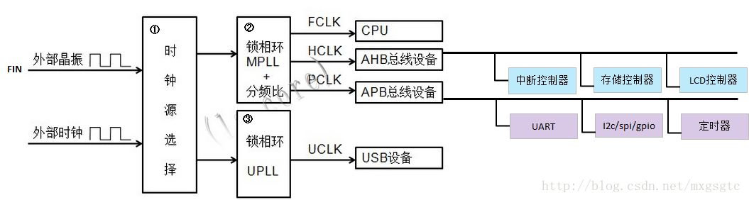
Introduction The system clock is the heart of the whole circuit. Understanding the system clock structure plays a very important role in the use of learning timers, UARTs, etc. In general, there are four main clocks related to the s3c2440 processor: FIN, FCLK, HCLK and PCLK 1.FIN: External input crystal frequency 2.FCLK: Mainly used for CPU core 3.HCLK: Mainly used for devices interconnected with AHB bus (such as memory controller, LCD controller, interrupt controller and DMA) 4.PCLK: mainly used on low-speed devices (such as timers, UART, ADB, etc.) interconnected with the APB bus.
Graphic clock
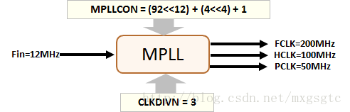
The s3c2440 processor system clock is divided into two parts. There is a clock input pin externally. The internal phase-locked loop is used to multiply the external input clock to the clock required by the processor. The external clock frequency is too high and is subject to external interference. Therefore, the general external clock frequency is relatively low, as shown below:
â– CLKDIVN: used to control the proportional relationship between FCLK, HCLK and PCLK

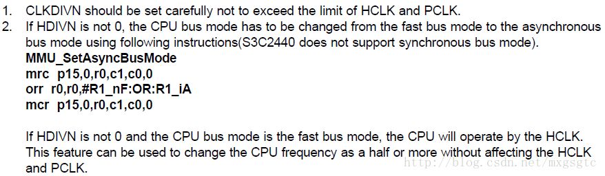
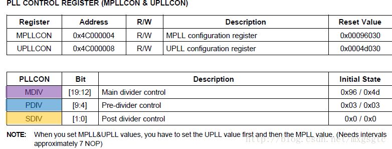
// LOCKTIME = 0x00ffffff; // Use the default value. CLKDIVN = 0x03 will be discussed below. // FCLK: HCLK: PCLK=1: 2:4, HDIVN=1, PDIVN=1/* If HDIVN is non-zero, The bus mode of the CPU should change from "fast bus mode" to "asynchronous bus mode" */__asm__("mrc p15, 0, r1, c1, c0, 0" /* Read control register */ "orr r1, r1, #0xc0000000" /* Set to "asynchronous bus mode" */"mcr p15, 0, r1, c1, c0, 0" /* Write control register */); MPLLCON = ((0x5c<<12)|(0x04 <<4)|(0x01))
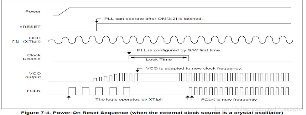
In the above code comment, about the assignment of LOCKTIME, what is going on here, or according to the manual
1
2
3
4
5
6
7
8
9
10
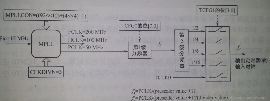
The timer is known from above. The timer is an ABP bus device and operates at the clock frequency of PCLK. The s3c2440 has five 16-bit timers. The timers 0, 1, 2, and 3 have pulse modulation (PWM) functions, so these 4 The timer is also called PWM timer. Timer 4 is an internal timer. There is no external output pin. Although the clock source of the timer is PCLK, it has to be divided by two internal dividers. In order to get the desired working frequency, then output the clock as the working of the timer, timer 0, 1 has one frequency divider, and the other three timers share another frequency divider, as shown below.
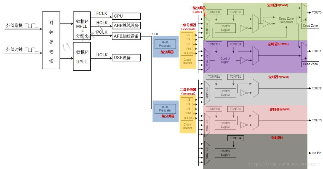
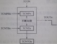
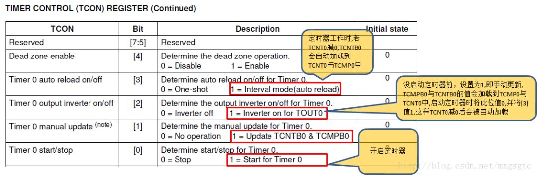
The working principle of the timer is described by taking Timer 0 as an example: 1. First, TCMPB0, TCNTB0 are attached with the initial value 2. Then, the timing controller TCON is set, and the first position of TCON is set to 1 (manually update bit), so TCMPB0 TCNTB0 is assigned to TCMPB0, TCNTB0 3. Start timer –> Set TCON bit 3 to 1 (when TCNT0 value is reduced to 0, TCMPB0 value is automatically loaded into registers TCMP0 and TCNT0), bit 0 is 1. (Turn on the timer) 4. At this time, the timer will be decremented by 1 count, that is, TCNT0 is decremented by 1 count. When TCMP0 is equal to TCNT0, the relevant register is defined in the manual after TOUT0 is flipped: ■TCON: For timing For 0:
The frequency division of the timer mentioned the use of timer 0, but did not mention the frequency required for its final work (how many numbers can be recorded in 1s)
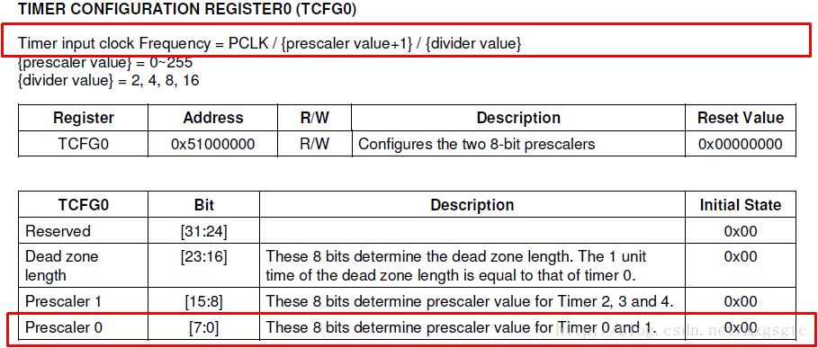

Void timer0_init(void) { TCFG0 = 99; // prescaler 0 = 99 TCFG1 = 0x02; // select divide by 8 TCNTB0 = 62500; // trigger interrupt once 1 second TCMPB0 = 0; TCON |= (1 <<1); // Manual update (update TCNTB0, TCMPB0 into TCNT0, TCMP0) TCON = 0x09; // Auto load, clear "manual update" bit, start timer 0 }
PWM function For timer 0, in the above example, TCNT0 1s is reduced to 0, then TOUT0 is inverted (level change), but timer 0 has a characteristic, that is, if TCNT0 is reduced to be equal to the comparison value TCMP0, Then TOUT0 also reverses, that is to say, the above example changes TCMPB0 to 31250, then TCNT0 is reduced from 62500 to 31250 (equal to TCMP0) TOUT0 is inverted once (0.5s), TCNT0 is reduced to 0 and reversed. Turn (use 0.5s), so that two inversions occur within 1s, so cycle, the output pin is inverted 0.5s once, that is, the duty cycle is 50% (waveform 0.5 seconds is high level, 0.5 second is low level) Such a looping waveform)
Void timer0_init(void) { TCFG0 = 99; // prescaler 0 = 99 TCFG1 = 0x02; // select divide by 8 TCNTB0 = 62500; // trigger interrupt once in 1 second TCMPB0 = 31250; TCON |= (1 <<1); // Manual update (update TCNTB0, TCMPB0 into TCNT0, TCMP0) TCON = 0x09; // Auto load, clear "manual update" bit, start timer 0 }
Note that if you change the above code TCMPB0=31250 to another value, such as TCNTB0 /4, the output waveform must change (for example, a waveform with a high level of 0.25 seconds and a low level of 0.75s). The duty cycle also changes, this is called the PWM function.

AC wall 5V 2A power adapter with multiple tips works for many small 5V electronics. Like Scanner, Router, Bluetooth speaker, Foscam Wireless IP Camera, CCTV camera, USB hub, bluetooth GPS Receiver, tv box, tablets, Baby Monitor, Graco Swing, Home Phone System, VoIP Telephone Routers, Serato DJ Controller, DVR, ADSL Cat, External battery, hubs, switches, Led Strip, String Lights, vibrator, Raspberry pi 3 Raspberry Pi A/A+/B/B+ Raspberry Pi Zero and more 5V devices. (5V ONLY)
Worldwide Input: 110-240V; Output: 5V 1000mA, 1.5A, 1.75A, 5V 1A, 5V 500mA, 5V 2.1A, Max 10W. DC Tip Polarity: Central Positive(+). Please read manual carefully before using 5vdc power supply.
Design-safeguard features against incorrect voltage, short circuit, internal overheating and overloading. This 5v Ac power supply charger is made from quality material to ensure the long lifetime. Power your 5v electronics perfectly and replaces lots of 5 volt power chargers
Package include: 1 x High Quality 5V 2A AC DC Power Adapter, 1 Set x Tips
5V Switching wall charger 6V Switching wall charger 9V Switching wall charger 12V Switching wall charger 15V Switching wall charger 19V Switching wall charger 24V Switching wall charger 36V Switching wall charger 48V Switching wall charger
Shenzhen Waweis Technology Co., Ltd. , https://www.szwaweischarger.com