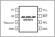
/ * Register declarations for DS5000 * / #define ACK 0 #define NACK 1 #define ADDRTC 0xd0 / * 2-wire addresses * / sbit scl = P1 ^ 0; / * 2-wire pin definitions * / sbit sda = P1 ^ 1 sbit RSTb = P0 ^ 2; void start2w (); void stop2w (); void writebyte2w (uchar d); uchar readbyte2w (int); void writebyte1672 (); void initialize_DS1672 (); void disp_clk_regs (); void en_tc () ; unsigned long date2day (uint, uint, uint, uint, uint, uint); void day2date (unsigned long); / * global variables * / void start2w () / * --------- Initiate start condition- --------- * / {sda = 1; scl = 1; sda = 0;} void stop2w () / * ---------- Initiate stop condition ------ ----- * / {sda = 0; sda = 0; scl = 1; scl = 1; sda = 1;} void writebyte2w (uchar d) / * ------------- ---------------- * / {int i; scl = 0; for (i = 0; i <8; i ++) {if (d & 0x80) sda = 1; / * Send the msbits first * / else sda ​​= 0; scl = 0; scl = 1; d = d << 1; / * do shift here to increase scl high time * / scl = 0;} sda = 1; / * Release the sda ​​line * / scl = 0; scl = 1; if (s da) printf ("Ack bit missing% 02X", (unsigned int) d); scl = 0;} uchar readbyte2w (int b) / * ------------------ ----------------- * / {int i; uchar d; d = 0; sda = 1; / * Let go of sda line * / scl = 0; for (i = 0; i <8; i ++) / * read the msb first * / {scl = 1; d = d << 1; d = d | (unsigned char) sda; scl = 0;} sda = b; / * low for ack, high for nack * / scl = 1; scl = 0; sda = 1; / * Release the sda ​​line * / return d;} void day2date (unsigned long x) / * ------ convert binary time to date format --- --- * / {int yrs = 99, mon = 99, day = 99, tmp, jday, hrs, min, sec; unsigned long j, n; j = x / 60; / * whole minutes since 1/1/70 * / sec = x-(60 * j); / * leftover seconds * / n = j / 60; min = j-(60 * n); j = n / 24; hrs = n-(24 * j); j = j + (365 + 366); / * whole days since 1/1/68 * / day = j / ((4 * 365) + 1); tmp = j% (( 4 * 365) + 1); if (tmp> = (31 + 29)) / * if past 2/29 * / day ++; / * add a leap day * / yrs = (j-day) / 365; / * whole years since 1968 * / jday = j-(yrs * 365)-day; / * days since 1/1 of current year * / if (tmp <= 365 && tmp> = 60) / * if past 2/29 and a leap year then * / jday ++; / * add a leap day * / yrs + = 1968; / * calculate year * / for (mon = 12; mon> 0; mon--) {switch (mon) {case 1: tmp = 0; break; case 2: tmp = 31; break; case 3: tmp = 59 ; break; case 4: tmp = 90; break; case 5: tmp = 120; break; case 6: tmp = 151; break; case 7: tmp = 181; break; case 8: tmp = 212; break; case 9 : tmp = 243; break; case 10: tmp = 273; break; case 11: tmp = 304; break; case 12: tmp = 334; break;} if ((mon> 2) &&! (yrs% 4)) / * adjust for leap year * / tmp ++; if (jday> = tmp) break;} day = jday-tmp + 1; / * calculate day in month * / printf ("% 04d% 02d% 02d% 02d:% 02d :% 02d ", yrs, mon, day, hrs, min, sec);} / * ---- convert date to elapsed days in binary ---- * / unsigned long date2day (uint yr, uint mo, uint da , uint hrs, uint min, uint sec) {unsigned long x; / * the following is broken down for clarity * / x = 365 * (yr-1970); / * calculate number of days for previous years * / x + = (yr-1969) >> 2; / * add a day for each leap year * / if ((mo> 2) && (yr% 4 == 0)) / * add a day if current year is leap and past Feb 29th * / x ++; switch (mo) {case 1: x + = 0; break; case 2: x + = 31; break; case 3: x + = 59; break; case 4: x + = 90; break; case 5: x + = 120; break; case 6: x + = 151; break; case 7: x + = 181; break; case 8: x + = 212; break; case 9: x + = 243; break; case 10: x + = 273; break; case 11: x + = 304; break; case 12: x + = 334; break;} x + = da-1; / * finally, add the days into the current month * / x = x * 86400; / * and calculate the number of seconds in all those days * / x + = (hrs * 1800); / * add the number of seconds in the hours * / x + = (hrs * 1800); / * add the number of seconds in the hours * / x + = (min * 60); / * ditto the minutes * / x + = sec; / * finally, the seconds * / return (x );} void writebyte1672 () / * ----------------------------------------- ------ * / {uchar Add; uchar Data; / * Get Address & Data * / printf ("Enter the Read AddressADDRESS:"); scanf ("% bx ", & Add); printf (" DATA: "); scanf ("% bx ", & Data); start2w (); writebyte2w (ADDRTC); writebyte2w (Add); writebyte2w (Data); stop2w ();} void initialize_DS1672 () / * ----------------------------------------- * / / * Note : NO error checking is done on the user entries! * / {Uchar a, b, c, d; uint yr, mn, dt, dy, hr, min, sec, day; unsigned long y; start2w (); writebyte2w ( ADDRTC); writebyte2w (0x04); writebyte2w (0x00); / * enable the oscillator * / stop2w (); printf ("Enter the year (1970-2099):"); scanf ("% d", & yr); printf ("Enter the month (1-12):"); scanf ("% d", & mn); printf ("Enter the date (1-31):"); scanf ("% d", & dt); / * printf ("Enter the day (1-7):"); * / / * scanf ("% d", & dy); * / printf ("Enter the hour (1-24):"); scanf (" % d ", & hr); printf (" Enter the minute (0-59): "); scanf ("% d ", & min); printf (" Enter the second (0-59): "); scanf (" % d ", & sec); y = date2day (yr, mn, dt, hr, min, sec); a = (y & 0xff); b = ((y >> 8) & 0xff); c = ((y >> 16) & 0xff); d = ((y >> 24) & 0xff); start2w (); writebyte2w (ADDRTC); / * write slave address, write 1672 * / writebyte2w (0x00); / * write register address, 1st clock register * / writebyte2w (a); writebyte2w (b); writebyte2w (c); writebyte2w (d); stop2w (); } void disp_clk_regs () / * ----------------------------------------- * / {uchar reg1, prv_sec = 99, reg2, reg3, reg4; unsigned long z; while (! RI) / * Read & Display Clock Registers * / start2w (); writebyte2w (ADDRTC); / * write slave address, write 1672 * / writebyte2w (0x00); / * write register address, 1st clock register * / start2w (); writebyte2w (ADDRTC | 1); / * write slave address, read 1672 * / reg1 = readbyte2w (ACK); / * starts w / last address stored in register pointer * / reg2 = readbyte2w (ACK); reg3 = readbyte2w (ACK); reg4 = readbyte2w (NACK); stop2w (); if (reg1! = prv_sec) / * display every time seconds change * / { z = reg4; z << = 8; z + = reg3; z << = 8; z + = reg2; z << = 8; z + = reg1; day2date (z);} prv_sec = reg1;} RI = 0; / * Swallow keypress to exit loop * /} void en_tc (dat) / * ----- enable the trickle-charger- ---- * / {start2w (); writebyte2w (ADDRTC); writebyte2w (5); writebyte2w (dat); / * enable the trickle-charger * / stop2w ();} main (void) / * ---- ------------------------------------------------- * / {uchar i, M, M1; RSTb = 1; while (1) {printf ("DS1672"); printf ("I Init DS1672 D / E Disable / Enable TC"); printf ("R Read Time W Write Byte "); printf (" Enter Menu Selection: "); M = _getkey (); switch (M) {case 'R': case 'r': disp_clk_regs (); break; case 'W': case 'w': writebyte1672 (); break; case 'D': case 'd': en_tc (0); break; case 'E': case 'e': en_tc (0xa6); break; case 'I': case 'i': initialize_DS1672 (); break;}}}
Push Button Switches
Push Button Switches
The Push Button Switches, also known as the control button (referred to as the button), is a low-voltage electrical appliance that is manually and generally can be automatically reset. The Push Button Starter Switch is usually used to issue a start or stop command in the circuit to control the turning on and off of electrical coil currents such as electromagnetic starters, connectors, and relays.
The On Off Push Button Switches refers to a switch that pushes the transmission mechanism with a button to make the movable contact and the static contact open or close and realize circuit switching. It is a master control device with a simple structure and a wide range of applications. In the electrical automatic control circuit, used to manually send control signals to control connectors, relays, electromagnetic starters, etc.

This Pushbutton Switches is a kind of electric device that is used to switch on and off the small current circuit when the action is released. Generally used in AC and DC voltage below 440V, the current is less than 5A in the control circuit, generally do not directly manipulate the main circuit can also be used in the interconnection circuit. In actual use, in order to prevent desperation, different marks are usually made on the buttons or painted with different colors, and the colors are red, yellow, blue, white, black, green, and the like.

The Momentary Push Button Switch could be divided into metal push button switches and LED Light Switches and ordinary snap button type, mushroom head type, self-locking type, self-resetting type, rotary handle type, with indicator light type, lighted symbol type and key type, etc., with single button and double Buttons. Generally, it adopts a water-storage structure, which consists of a button cap, a return spring, a static contact, a moving contact and a casing. It is usually made into a composite type, and has a pair of normally closed contacts and normally open contacts, and some products can pass. The series connection of multiple elements increases the number of contact pairs. There is also a self-contained button that automatically holds the closed position when pressed, and can be turned on only after the power is turned off.
When the Metal Switches is not pressed, the movable contact is connected with the upper stationary contact. The pair of contacts is called a normally closed contact. At this point, the movable contact is disconnected from the following static contact. The pair of contacts is called a normally open contact: the button is pressed, the normally closed contact is open, the normally open contact is closed, and the button is released. Restore the original working state under the action of the return spring
Push Button Switches,Push Button On Off Switch,Push Button Switch Types,Square Push Button Switches
YESWITCH ELECTRONICS CO., LTD. , https://www.yeswitches.com
![<?echo $_SERVER['SERVER_NAME'];?>](/template/twentyseventeen/skin/images/header.jpg)