![<?echo $_SERVER['SERVER_NAME'];?>](/template/twentyseventeen/skin/images/header.jpg)
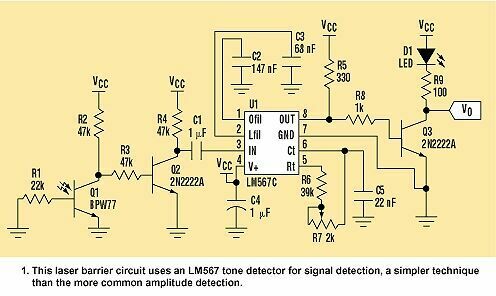
The laser barrier consists of a transmitter and a receiver. The transmitter is based on the LM555 timer and can operate in various modes. It drives a laser diode with a frequency square wave f0. The receiving circuit of Figure 1 captures the optical signal through a BPW77 phototransistor (Q1), which then converts the Q1 collector voltage into a square wave. This step is required due to the frequency response of Q1.
This article refers to the address: http://
In this circuit, the detection is independent of the amplitude. The LM567 audio detector consists of a Class I phase comparator and a voltage controlled oscillator. When the signal frequency on the input port (pin 3) is within the range of f0 ± (BW/2), the audio detector produces a logic zero state on its output (pin 8). The central frequency f0 and the detection bandwidth BW perform the functions of the circuit parameters.
The center frequency is:
 |
In the circuit, f0 is set to 10 kHz and is well tuned by potentiometer R7. The BW is set at 1.2 kHz. The value of the center frequency is limited by the speed of the phototransistor, while the BW is defined by a system response time requirement. C2 and C3 set the bandwidth detection to 12% of f0. NP0 capacitors, such as a polyester type, are used due to their stability over a wide temperature range. The lock time of the audio detector is between 1 and 10 cycles of the center frequency, so the maximum response time is 1 ms. Q3 drives LED D1 to display the barrier status.
 |
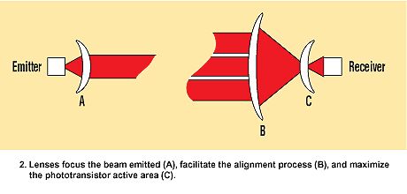
The optical path is critical to proper operation. As shown in Figure 2, the lens focuses the emitted beam (A) and pushes the calibration process (B). The lens expands the active area of ​​the phototransistor to a maximum (C). This barrier can be used to accurately detect a point that interrupts the optical path. This can be used to detect a small object in an industrial environment or to detect high speed movements during a race.
 |
 |
Solar Home Lighting System Kit
SHENZHEN CHONDEKUAI TECHNOLOGY CO.LTD , https://www.szfourinone.com