![<?echo $_SERVER['SERVER_NAME'];?>](/template/twentyseventeen/skin/images/header.jpg)
PSoC sensor application platform
This article refers to the address: http://
In an embedded system, the control chip mainly processes two types of signals, one is a digital signal and the other is an analog signal. The analog signal is usually from the sensor. Getting accurate signals from these analog sensors is not an easy task. The analog output signal usually has a small amplitude, so a signal amplifier is required. After the signal is amplified, the noise is also amplified and an analog low-pass or band-pass filter is required for filtering. If multiple sensors are used at the same time, an analog MUX is also required. In addition to this, it is also possible to use comparators and D/A converters.
In traditional design, the controller is only used to process data, communication and control functions between systems. If your design is also in this traditional way, you will face some challenges. These challenges are mainly from separate analog devices and fixed-function MCUs. First of all, from the perspective of system design, with the speed of market changes and the increase of user requirements, a flexible and hard-designed platform is necessary, and separate analog devices and fixed-function MCUs are far from meeting the constantly updated design requirements. And limited R&D time to market. Second, dealing with sensor noise requires a complex mixed-signal solution that typically requires amplifiers, filters, ADCs, comparators, and DACs. For traditional designs, it is necessary to consider a large number of independent separation devices, which will become a burden in terms of product cost and production cost.
The highly integrated and flexible PSoC effectively addresses these challenges. What functions can PSoC achieve? The single-chip PSoC can realize the input and signal processing of various analog sensing signals at the input end of the signal, and can also realize the design of the popular capacitive touch sensing. In terms of control functions, PSoC can realize various fan and motor control and power control, and also supports a variety of complex communication interfaces. PSoC applications are ubiquitous. PSoC is used in consumer electronics, white goods, medical, automotive, and industrial control products. Currently, PSoC has more than 8,100 customers worldwide and shipped more than 400 million.
What kind of system is PSoC? PSoC is the acronym for Programmable System-on-Chip. It is not a pure MCU. In addition to the 8-bit MCU core, Flash and SRAM, it also includes programmable digital and analog modules. It is a true system-on-chip.
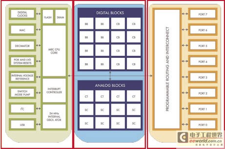
Figure 1 PSoC product block diagram

Figure 2 Ultrasonic signal transmission
As can be seen from Figure 1, the entire PSoC system consists of MCU cores, Memory, digital systems, analog systems, and other system resources. The left part of the figure is the structure of a common microcontroller, including the clock source, Flash, SRAM and MCU itself. On the right are some programmable GPIOs. The middle part is the PSoC feature, which can be programmed with digital modules and analog modules. The advantages of PSoC are also here. These programmable digital and analog modules can be configured with different functions such as UART, ADC, filter and PWM. In addition, these modules can be reconfigured to perform different functions and can be modified at any time. PSoC supports the dynamic configuration feature, the same resources can be configured into different user modules at different times, which can save a lot of resources. Digital and analog modules can be interconnected with external pins and are programmable. So with PSoC, engineers can basically complete the design of a system.
PSoC's analog capabilities are very powerful, enabling a variety of analog devices such as ADCs, DACs, filters, etc. CapSense is also implemented with analog functions. The various applications of sensors, control applications, etc. are all realized by the functions of these analog modules.
PSoC differs from fixed-function MCUs in that it is highly integrated, flexible, and programmable in real time. These advantages help designers reduce costs, get products to market quickly, and increase market share. Among them, the high level of integration is because PSoC is a system-level solution with programmable digital and analog modules, 8-bit controllers, and Flash and SRAM. Flexible use means that you can use the set of visual embedded design tools. Designed with integrated PSoC Designer, design flexibility, time savings, and design modifications even at the last minute; real-time programmability means that PSoC provides a range of analog and digital user modules (eg amplifiers, filters, comparators, timers) , counters, etc.), users can configure as needed, or dynamically configure. In short, PSoC, as a flexible system-on-a-chip, helps increase the value of the product.
Ultrasonic sensor and parking sensor system
Ultrasonic sensors are used in a variety of applications. Common applications include flow meters, tool parts cleaning, and reversing radar. The ultrasonic sensor converts the electrical signal at the ultrasonic frequency into an ultrasonic sound wave through the ultrasonic transducer in the ultrasonic sensor, and the ultrasonic sensor emits the ultrasonic sound wave according to a certain direction, and is rebounded back when the ultrasonic sound wave encounters an obstacle, and then is ultrasonically detected. Accepted, converted by an ultrasonic transducer into an electrical signal. Since the speed of sound is a known constant, the distance can be calculated by the time of the rebound.
Ultrasonic sensors can be divided into two types according to the type of package, which are open type and sealed type. Among them, the open type has a wider propagation area and a longer detection range, which is suitable for application in an open environment. The sealed sensor has a small propagation area and a general detection distance. It is suitable for use in liquids and needs to be in close contact with solid materials.
The use of ultrasonic sensors is similar to radar, which performs two main tasks: transmitting ultrasonic sound waves and receiving ultrasonic sound waves. Sending ultrasonic waves is relatively simple, as long as the ultrasonic waves sent by the ultrasonic sensors are pulse width modulated, and the timer is turned on at the same time. The receiving part is more complicated, and the signal needs to be adjusted so that the controller can correctly recognize the reflected ultrasonic wave, determine the receiving time and stop the timer technology, and then calculate the distance according to "distance = time x speed of sound". From Figure 2, you can see how the signal is sent out. The PWM signal generated by the control chip is amplified by the power amplifier, sent to the ultrasonic sensor for pulse width modulation, and then the timer is turned on. The process of receiving and processing ultrasonic signals is relatively complicated (Figure 3). The signal input from the ultrasonic sensor is amplified by PGA. After filtering the noise by the band-pass filter, the signal is compared with the DC offset, and the modulated signal is output, and then sent to the low-pass filter to generate a modulated signal. The envelope. The envelope is then used by a comparator or an AD converter to determine if it is a true bounce signal, while stopping the timer, and finally calculating the distance by the value of the counter and the speed of sound.
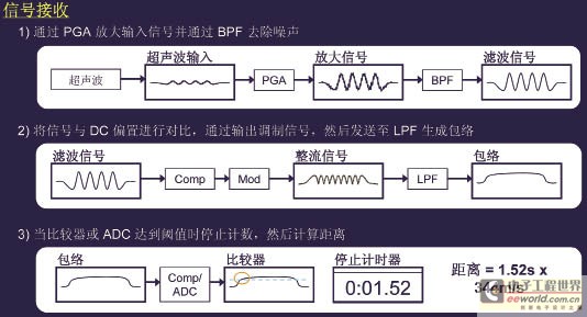
Figure 3 Ultrasonic signal reception
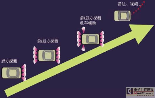
Figure 4 Development trend of reversing radar
Figure 4 shows the development trend of reversing radar. It can be seen from the figure that the initial reversing radar has only rear detection. The current reversing radar not only realizes front and rear detection, but even the left and right sides can detect it. There are also some more advanced technologies that have been used in high-end cars.
Low-end reversing radar system
The reversing radar system generally consists of two parts, a probe part and a main control part. The probe section is typically mounted on the rear or sides of the car, while the main control section is located at the front end of the car, close to the driver of the car. The probe section of the low-end reversing radar (Fig. 5) usually contains only ultrasonic sensors, while the main control section includes the CPU and all peripheral circuits. The probe and main control board are connected by a conductive line to transmit the transmit and echo signals, and one main control board has 3 to 4 probes. The low-end reversing radar system is usually low in cost, mostly using discrete components, and the integration is also low, so the performance is poor, and the effective measurement distance is less than 1.5m. In addition, the alarm also uses a simple buzzer.
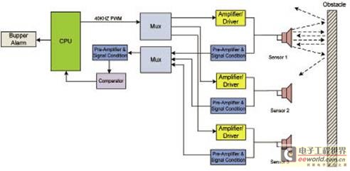
Figure 5 Block diagram of the low-end reversing radar system
Mid-end reversing radar system
The mid-end reversing radar system includes, in addition to the ultrasonic sensor on the probe, an amplification and driving circuit for transmitting signals, and an amplification and signal conditioning circuit for the received signal, which can reduce the influence of noise introduced by the signal in long-line transmission. In addition, on the control board, a two-stage amplification and bandpass filter is used to improve the performance of the measurement. The measured distance is usually displayed by means of a digital display with alarms and prompts for sound.
High-end reversing radar system
Figure 7 is a system block diagram of a high-end reversing radar system. It can be seen that some functional modules that are originally at the main control end are transferred to the probe end. It is characterized by a signal amplifying circuit and a processor on the probe, and the measurement signal is processed on the sensor, so there is no long-line transmission of the existing signal. Interference problem. In addition, it can individually calibrate each sensor to communicate with the host CPU via LIN or other serial means. Because the probe portion is usually small in size, in order to achieve signal amplification and processing on the probe, a highly integrated device is needed to facilitate integration of the sensor and the PCB.
Figure 8 shows the requirements for the coverage area of ​​the reversing radar sensor, which requires a minimum of 100° in the range of 70 ± 5 cm in the horizontal direction and a minimum of 40 ° in the range of 100 ± 5 cm. In the vertical direction, the minimum is 60° in the range of 50±5 cm; in the range of 110±5 cm, the minimum is 20°.
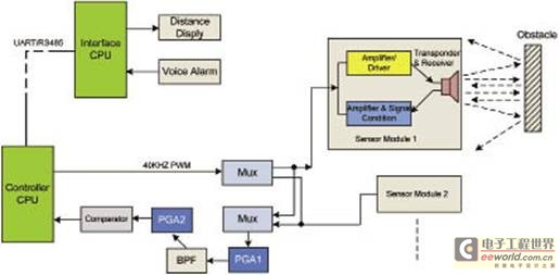
Figure 6 Block diagram of the mid-end reversing radar system
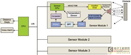
Figure 7 Block diagram of the high-end parking radar system
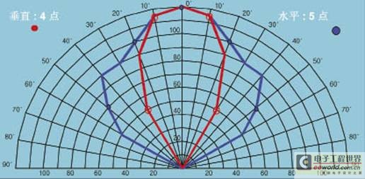
Figure 8 Reversing radar sensor coverage area requirements
Cypress Reversing Radar Control System Reference Design
The main reasons for Cypress's reversing radar control system using PSoC system are: 1. Its resources are flexible, PSoC's module resources are programmable, and can be reconfigured for different customers and different positioning products; 2. High integration, integration Analog modules such as PWM w/DB, comparator, A/D converter PGA, etc., high analog integration; 3. It requires almost no external components, reducing BOM cost and reducing board size; 4. Its IP Strong protection and difficult to copy.
The PSoC reversing radar controller uses the CY8C24633 chip as the main control chip. The chip uses the M8C processor and runs at up to 24M with an 8×8 multiplier and a 32-bit accumulator. The operating voltage range is 3V~5.25V, and the temperature range is industrial grade: -40°C~85°C. The PSoC chip includes 4 digital blocks and 4 analog modules (2CT/2SC). It also features a high speed 8-bit SAR AD converter optimized for motor control.
Figure 9 shows the hardware block diagram of the Cypress reversing radar system, using CY8C24633 for the main control board. The design uses a transceiver-integrated sensor and adds a primary amplifier circuit to the sensor. The drive signal is a 40 kHz pulse signal. Each sensor is connected to the main control board by a 3-wire connection, and up to 6 sensor inputs can be connected. The AC signal is level raised to better handle the echo signal. The internal analog blocks can be configured as PGAs, comparators, and bandpass filters, and interconnected within the device. The main control board and the display are connected through a serial port, and the display digitally displays the detection distance.
Figure 10 shows the configuration of the PSoC internal module and the routing of the signals. As you can see, the four digital blocks are configured as PWM timers, timers, and serial port generators. The four analog modules are configured as two PGA amplifiers and one bandpass filter, and the routing of the signals can be seen clearly from the figure.
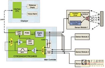
Figure 9 Cypress reversing radar control system hardware block diagram
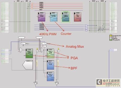
Figure 10 PSoC internal module configuration
Home Fragrance Diffuser takes advantage of the unique charm of the fragrance, which extends the communication from the sense of sight and hearing to the sense of smell to a deeper level. The fragrance is used to optimize the environment, so that customers can fully feel the warmth service and increase the customer's goodwill and satisfaction. Home Aroma Diffuser is suit for home, hotel rooms, lobby, aisle, office, spa and other places.
China Home Diffuser ,Home Oil Diffuser,Home Fragrance Diffuser,Home Aroma Diffuser , DITUO offered that you can trust. Welcome to do business with us.
Home Diffuser
Home Diffuser,Home Oil Diffuser,Home Fragrance Diffuser,Home Aroma Diffuser
Shenzhen Dituo Electronic Co.,Ltd. , http://www.sz-dituo.com