![<?echo $_SERVER['SERVER_NAME'];?>](/template/twentyseventeen/skin/images/header.jpg)
The difficulty in assessing the uncertainty of measurement is to clarify the uncertainty component of the measurement system, without repeating or missing. This paper describes the uncertainty component of the integrating sphere luminous flux measurement system in combination with the description of CALiPER lumen measurement uncertainty.
In the actual evaluation process of uncertainty, it is necessary to understand the measurement process and the composition and principle of the measurement system. Factors such as equipment, instrumentation, environment, and personnel included in the measurement process may include uncertainties in the measurement results. Therefore, the measurement system is analyzed from the input, processing, and output stages of the system to measure the process. As the main line, the components of the measurement uncertainty can be obtained.
1. Integrating sphere luminous flux measurement process
In the luminous flux measurement process of the integrating sphere, it is first necessary to check the integrity of the system and check whether the environment meets the requirements. Then the integrating sphere is closed, all internal light sources are turned off, the system is reset to zero, and the effect of dark current is eliminated. Then measure its self-absorption coefficient, and then use the reference standard lamp to calibrate the system. The power supply provides a stable and appropriate current/voltage to make the reference standard lamp in a stable measurement environment emit light normally. The generated light is reflected multiple times in the integrating sphere and evenly distributed on the inner spherical surface of the integrating sphere. The higher the reflectivity of the integrating sphere, the less energy is lost during the reflection process. At the same time, the reflective layer should respond well to the full wavelength. The spherical error of the integrating sphere should also be controlled within a certain range. The photometer uses the principle of photoelectric effect. In the measurement range, its output response (voltage or current) can be proportional to the luminous flux, and the optical signal in a certain unit area of ​​the integrating sphere is collected and converted into an electrical signal through a signal processing system. The calculation gives the corresponding value, as is the measurement of the old test lamp. Finally, the ratio of the two values ​​and the calibration luminous flux and self-absorption coefficient of the reference standard lamp are substituted into the formula to measure the value of the required luminous flux of the test lamp.
Figure 1 shows the composition of the integrating sphere luminous flux measurement system.

2. Luminous flux calculation formula
The following formula gives the formula for calculating the luminous flux ,, which fully reflects the various influencing factors. In the formula, the subscript R represents the reference standard lamp, and the test lamp has no subscript.
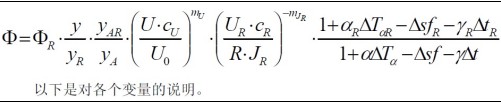
The following is a description of each variable.
1) R ï† : Refer to the calibration luminous flux of the standard lamp, the value of which is given by the calibration certificate.
2) RJ: Refer to the calibration working current of the standard lamp, the value of which is given by the calibration certificate.
3) RU: Used to measure the voltage value on the shunt resistor R of RJ. The uncertainty is class A and needs to be obtained by multiple measurements. The nominal value and uncertainty of the resistor R are given by the calibration certificate. During the test, if the reference standard lamp gives the calibration working current, the calibration needs to adjust the working current to the calibration working current. At this time, the voltage value on the shunt resistor R in the circuit should be measured with a voltmeter, and the actual working current can be obtained through calculation. .
4) U: Input voltage value when the test lamp is working. The uncertainty should consider the stability of the voltage supplied by the power supply, the accuracy of the adjustment, and the uncertainty of the monitoring meter.
5) 0 U : The rated voltage of the test lamp, for example 220 V. When the test lamp is working, it is generally necessary to adjust the working voltage to the rated voltage to obtain a good working condition of the lamp.
6) c: The meter calibration constant, usually expressed as a fraction of the nominal value, the value of which is given by the meter calibration certificate. U c in the formula refers to the calibration constant of the voltmeter used to measure the operating voltage of the test lamp. R c in the equation refers to the calibration constant of the voltmeter used to measure the voltage across the shunt resistor R.
7) U m : The effect of the input voltage on the luminous flux. In the case of incandescent lamps, U m is 4; self-ballasted compact fluorescent lamps or SSL light outputs are insensitive to changes in input voltage and can be ignored.
8) JR m : Effect of current on luminous flux. For incandescent or halogen lamps operating at a correlated color temperature (CCT) close to 2,856 K, the JR m is 7.
Note: Theoretically the light output and  In proportion, where the filament temperature T is in absolute temperature.
9) y: The signal measured by the photometer when the lamp is operating at a steady current. Its uncertainty is class A and needs to be obtained by multiple measurements. R y in the equation is the signal measured by the photometer when the reference standard lamp is operating at the calibrated operating current.
Note: The self-absorption coefficient α is the lumen related signal A y obtained when the test lamp is installed in the integrating sphere but not turned on when the auxiliary light is on, and the reference standard light is installed in the integral when the auxiliary light is on. The ratio of the lumen related signal AR y obtained in the ball but not turned on, ie  . It mainly considers the influence of the reflection and absorption of light on the structure and surface materials of the lamp on the measured signal.