![<?echo $_SERVER['SERVER_NAME'];?>](/template/twentyseventeen/skin/images/header.jpg)
Urban Public Transport Advertisement Information Transmission Based on Broadcast Data System
Broadcast data system (RDS) is a scheme that uses FM multiplexing technology to transform the existing FM broadcast system and uses the remaining frequency band of FM broadcast to realize data broadcasting. By analyzing the basic data structure of RDS, the traditional cyclic redundancy check (CRC) operation is transformed into a three-byte recursive algorithm and the table look-up method is used for fast calculation, which is realized under the premise of limited operation speed and resources RDS data group synchronous calculation method and program flow, and how to use RDS transparent data channel to transmit city bus advertising information and other content.
Keywords: broadcast data system; data structure; data group synchronization; transparent data channel; information transmission
0 Introduction The Radio Data System (Radio Data System, RDS) uses FM multiplexing technology to transform the existing FM broadcast system, using FM stereo or mono broadcast 57 kHz subcarriers in the frequency range of 87.5 to 108 MHz. Transmitting data information, its transmitting and receiving devices are fully compatible with existing FM broadcasting systems. The bandwidth occupied by the RDS signal is narrow, and the data transmission rate is only 1187. 5 b / s, which is very suitable for transmitting real-time text information that does not require high data rates. The "city bus advertising information display screen" designed here uses the transparent data channel of RDS to realize the transmission of text advertising information.
1 System composition and working principle The composition of "RDS-based city bus advertising information display screen" is shown in Figure 1.
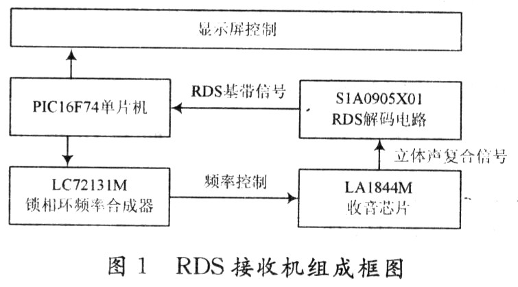
In the design of the RDS signal reception, the programmable phase-locked loop frequency synthesizer LC72131M and the radio chip LAl844M of Japan Sanyo Co., Ltd. are used as the main circuit to receive the FM broadcast signal.
The stereo composite signal output from the frequency discriminator in the LAl844M chip is sent to the RDS decoding circuit S1A0905XOl for separation, and the RDS baseband signal is extracted and directly input into the PICl6F74 single-chip microcomputer. Data synchronization is processed by software, and then the corresponding advertisements and text information are displayed on the bus On the front strip LED display.
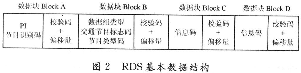
2 Structure of the RDS data group Figure 2 shows the basic data structure of the RDS baseband signal. The largest element in the structure is called a data group (Group) and consists of 104 bits. Each group is composed of 4 data blocks (Block) of 26 bits each. Each data block is composed of an information code and a check code. The information code is 16 bits and the check code is 10 bits. The offset in the figure represents the position of each data block in the data group.
The main features of the RDS data structure can be summarized as follows:
(1) The first data block of each RDS data set must contain a program identification code (Programme IdenTIfleaTIon, PI code). The PI code is established to determine the same program broadcast in different regions or even different countries. It is not for the purpose of displaying program information, but the ID of a particular program, which makes the program different from other programs. An important application of the PI code is that when the current frequency point reception is poor, the RDS receiver can automatically tune to other frequency points that are broadcasting the same program to ensure listening quality. This function is particularly important in vehicles or mobile receiving devices.
(2) Traffic program identification code (Traffic Programine IdenTIfi-caTIon, TP code) and program type code (Programine Type, PTY code) always appear in the fixed position of the second data block of each RDS data group, regardless of the data group Version.
The TP code is a switch mark, which is used to indicate whether the radio program broadcast at the frequency point tuned to now contains traffic information, including the traffic information being broadcast and to be broadcast here.
The function of the PTY code is to tell the listener what type of program is being received, such as sports programs, entertainment programs, etc. in the form of characters.
(3) The beginning 4 bits of the second data block of each RDS data group is the data group type flag. In the RDS specification, the data group is divided into 16 categories from 0 to 15 according to the difference of the 4-bit flag, and each category is divided into two versions of A and B according to the difference of the 5th bit value.
In the RDS specification, there are a total of 32 types of RDS data set types of up to 16 categories in two versions, each targeting different data characteristics and functions. It should be noted that these different types of data sets are sent at different frequencies according to the importance of the information carried and the differences in the types of information.
Among the RDS systems that have already begun to operate in the world, none have fully realized all the functions that the RDS system can have, but are selectively implemented according to the specific local conditions. Similarly, in the design process of the RDS receiver, based on cost-effectiveness and practical considerations, some functions of the RDS are also targeted.
3 Acquisition of RDS data group synchronization In the RDS data block, a variant of the standard CRC check is used, and its generating polynomial is: ![]()
The 16-bit information word is divided modulo 2 by g (x), and the resulting remainder is then added to the data block offset using modulo 2 addition to form the transmitted 10-bit check word.
Because the RDS data group and data block are continuously sent without any interval, to complete the synchronization operation of the RDS data group, it is necessary to perform a CRC on the newly composed 26-bit data stream after each new data bit is received Check operation. In order to ensure the continuity of data processing, the operation must be completed before the next data bit arrives, that is, the operation must be completed within 842 μs (that is, one RDS symbol period).
Since the generator polynomial G (x) of the CRC check in RDS occupies two bytes in the operation of the single-chip microcomputer, according to the principle of CRC check, its operation in the 8-bit single-chip microcomputer is actually a three-byte sequence recursive operation. The remainder obtained from each operation is added to the next three-byte sequence for modulo two division. By analogy, each recursive operation is a calculation of a three-byte sequence. Therefore, how to operate the three-byte operation simply and quickly is the key to the algorithm.
When it comes to simplicity and quickness, people naturally think of the table lookup method, which is to calculate all the remainders of the three-byte sequence in advance and put them in a table called the remainder table for reading at any time. However, such a table is too large, requiring 224 16-bit units, that is, occupies 225 bytes of storage space, which is unacceptable for the microcontroller, so try to reduce the storage space occupied by the table as much as possible.
Let a three-byte sequence Tabc = [abc], a three-byte sequence Ta00 = [a OO] and a two-byte sequence Tbc = [bc]. The relationship between them can be expressed in the form of polynomials as Tabc (x) = Ta00 (x) + Tbc (x), therefore, for Ta00:
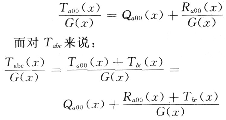
Among them, Qa00 (x) is an integer and has nothing to do with the remainder; while Ra00 (x) and Tbc are two-byte sequences, so their sum (modulo 2 addition, that is, XOR operation) is still a two-byte sequence Therefore, it is the residual Rabc of Tabc, namely:
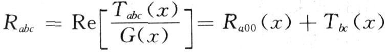
In this way, the operation of the three-byte sequence Tabc = [abc] can be decomposed into two steps to complete:
(1) Read the remainder Ra00 = [ha00 laO0] of Ta00 = [a O 0] by checking the remainder table;
(2) Perform an exclusive-OR operation on Ra00 and [bc] to obtain the remainder of [abc] Rabc = [habc labc].
Since [a 0 0] has only one byte that is not zero, the remainder table only requires 256 cells, or 512 B of storage space.
The PIC16F74 microcontroller is used in the design process of the RDS receiver. Its ROM space is only 16 KB. It also needs to complete many other functions such as display control and electronic tuning control. The storage space is very tight, so the residual table needs to be compressed. .
Decompose Ta00 = [aoo] into Ta00 = [e OO] and Tf00 = [f 0 O], and make the upper nibble of byte e the same as the upper nibble of a but the lower nibble is zero, At the same time, the content of the lower nibble of byte f is the same as the content of the lower nibble of a but the content of the upper nibble is zero, and then the residual table of Ta00 is replaced with the generated residual table of Ta00 and Tf00. Since only half of the bytes in Ta00 and Tf00 are not zero, each residual table only needs 16 units, that is, 32 bytes. The two residual tables occupy a total of 64 bytes, which can meet the PIC16F74 microcontroller. Storage space requirements.
A fast algorithm to implement CRC check is only one of the prerequisites for synchronizing RDS data signals. Since the synchronization information of the RDS data signal is included at the end of each 26-bit data block, the method of receiving data first and then performing synchronization operation must be adopted. In the general register of the PICl6F74 single-chip microcomputer, a 4-byte buffer is specifically set for receiving data. For each bit of data received, the data buffer is shifted according to the principle of first-in first-out (FIFO), and then the nearest CRC check operation is performed on the received 26-bit data, and the operation result is compared with the RDS data block offsets A, B, C, and D. If it is found to be the same as one of them, the quasi-synchronous state is considered. Due to the randomness of the received data, the probability of calculating the data block offset in a single 26-bit data stream is relatively large, so after further detection must be performed to enter the quasi-synchronous state, the quasi-synchronous counter starts to count the received data bits. Count, when another set of 26-bit data is received, perform another CRC check operation, if the operation result is one of the RDS data block offsets A, B, C, D, and the last detected The offset of the RDS data block is in a sequential relationship, and it can be considered that the synchronization of the RDS data signal has been acquired.
After acquiring synchronization, there is no need to perform a CRC check every time 1 bit of data is received, but only to perform a check operation after receiving a complete 26-bit data to detect whether the data is transmitted incorrectly and obtain the deviation of the data block. Shift amount.
4 The transmission of text information in the RDS transparent data channel Since the RDS receivers involved here are mainly used for the text signal transmission of bus advertising display screens, the two types of data suitable for text information transmission in RDS, namely open data, are mainly discussed Applications and transparent data channels.
Open Data Application (Open Data Application, ODA) is an important part of the RDS data type, which gives the RDS system great flexibility to achieve various specific functions. Open data applications only stipulate the format of the data set, but there are no specific regulations on the contents. Due to the regional characteristics of FM broadcasting, different places can make specific regulations on the content of open data applications according to their different needs. Of course, the receiving end must also be able to understand these specific regulations. In practical applications, open data structures are often used for special purpose data broadcasting, such as wireless paging, stock market information, etc. In the relevant standards of RDS, it is stipulated that open data applications should be registered with the standard-setting department.
Compared with open data applications, transparent data channels (Transparent Data Channels, TDC) make RDS functions more flexible. The reason why it is called transparent means that it can transmit data of any length and any format through it. Figure 3 shows the data group structure of the transparent data channel.
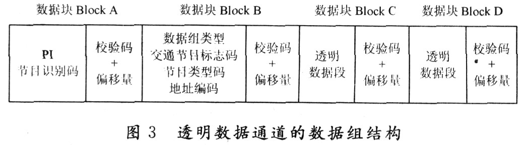
The address coding in Figure 3 refers to the sub-channel number of the transparent data channel, which consists of 5 binary digits. In other words, the transparent data channel can accommodate up to 32 channels of data for simultaneous transmission.
In view of the flexibility and scalability of the transparent data channel in the realization of functions, the designed "RDS-based urban bus advertising information display screen" uses a transparent data channel for data transmission. Since it can accommodate up to 32 data transmissions, it also means Advertising operators can transmit multiple sets of information on one FM channel at the same time, which not only helps to reduce operating costs. According to the needs of advertisers, specific advertising information content can be displayed on specific bus lines in a targeted manner, which improves the flexibility of advertising information delivery.
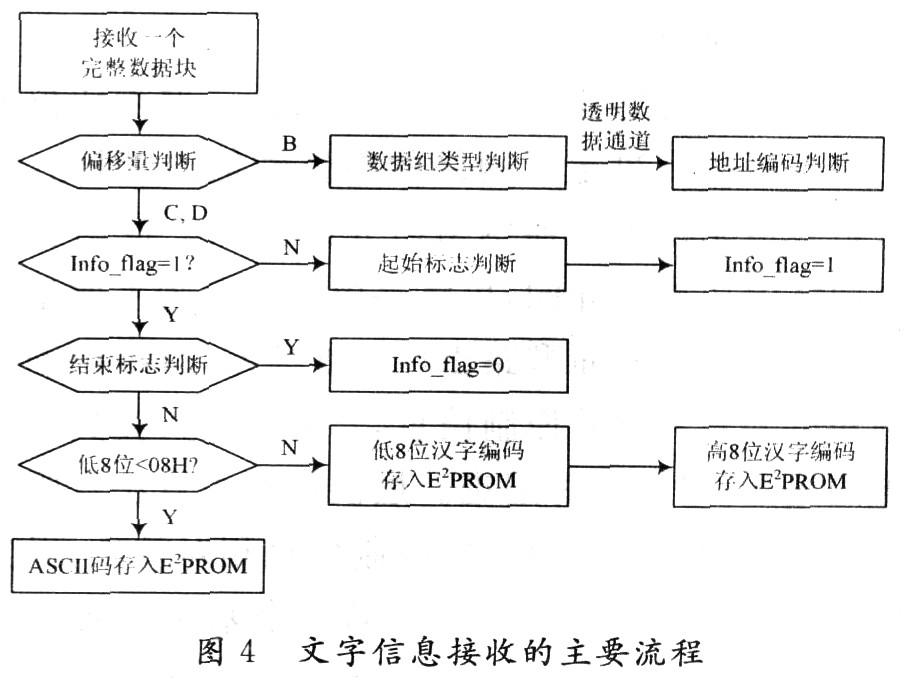
The RDS specification does not specify the format and length of the data transmitted in the transparent data channel, so the data transmission protocol can be designed according to actual needs. Because the system transmits ASCII codes (less than 80H) and Chinese character encoding such as numbers, English, and punctuation marks, for 16-bit Chinese character encoding, a 16-bit transparent data segment is required for transmission. For ASCII characters, only one The lower 8 bits of the transparent data segment are transmitted, while the upper 8 bits are reserved. Since the Chinese character encoding starts at OAlH for each byte of data, it will not be confused with ASCII characters less than 80H.
To facilitate signal processing, the start mark 7EH is set at the beginning of each text message, corresponding to the ASCII code character "~"; the end mark ODH is set at the end of each text message, which corresponds to the carriage return character of the ASCII code.
The main process of receiving a complete text message is shown in Figure 4.
5 Conclusions In the design process of "RDS-based city bus advertising information display screen", through careful analysis of the RDS data structure, under the premise of limited processing speed and computing resources, the real-time operation of the RDS data group synchronization calculation was successfully solved Sexual issues, the transmission of text information in the RDS transparent data channel has been achieved, and satisfactory results have been achieved in the actual operation.
RDS, as a data transmission method developed by relying on traditional media, is constantly improving and developing itself. As more new technical methods are applied to the RDS system, the connotation of RDS is also constantly expanding, and its application field will continue to expand.
Protective Suit,Protective Personal Suit,Medical Isolation Gown,Disposable Isolation Gown
Ningbo Anbo United Electric Appliance Co.,ltd , https://www.airfryerfactory.com