![<?echo $_SERVER['SERVER_NAME'];?>](/template/twentyseventeen/skin/images/header.jpg)
There are always more or less problems in the design and development of communication modules, so we should pay more attention to details when designing, to avoid rework, I will share my design experience for everyone, I hope to help everyone.
Wireless communication module design skills
The module must be modulated with signals to work properly. Common fixed-code encoding devices such as PT2262/2272 can be connected as long as they are directly connected. It is very simple because it is a special encoding chip, so the effect is very good.
Another important use of the module is to use the microcontroller to achieve data communication. There are certain skills:
1, a reasonable communication rate
The maximum transmission data rate of the data module is 9.6KBs, which is generally controlled at about 2.5k. Excessive data rate will reduce the receiving sensitivity and increase the bit error rate or even work at all.
2. Reasonable information code format
When the MCU and the module work, they usually define the transmission protocol by themselves. Regardless of the modulation method used, the format of the information code to be transmitted is very important, which will directly affect the reliable transmission and reception of data.
Code group format recommendation
Preamble + sync code + data frame, the preamble length should be greater than 10ms to avoid background noise, because the first bit of data received by the receiving module is easily interfered (ie, zero-level interference) and the received data is caused. error. Therefore, using the CPU code can add some garbled code before the data identification bit to suppress zero-level interference. The sync code is mainly used to distinguish it from the preamble and data. There are certain characteristics, so that the software can identify the synchronization code through a certain algorithm and prepare for receiving data.
Data frames should not use non-return to zero code, but not longer 0 and longer 1. Manchester code or POCSAG code is used.
3, the interference of the single chip to the receiving module
When the MCU simulates 2262, it is generally normal. However, when the MCU simulates 2272 decoding, it usually finds that the remote control distance is shortened a lot. This is because the multiplier of the clock frequency of the MCU will interfere with the receiving module. The electromagnetic interference of the 51 series MCU is relatively large, 2051 Slightly smaller, the PIC series is smaller, we need to use some anti-interference measures to reduce interference. For example, the single-chip microcomputer and the remote control receiving circuit are respectively powered by two 5 volt power sources, and the receiving board is separately powered by a 78L05. The clock area of ​​the single chip microcomputer is far away from the receiving module, the working frequency of the single chip microcomputer is lowered, and the shielding is added in the middle.
It is better to make an isolation circuit when receiving the module and the 51 series MCU interface, which can better suppress the electromagnetic interference of the MCU to the receiving module.
When the receiving module works, it generally outputs a high-level pulse, which is not a DC level, so it cannot be tested with a multimeter. When debugging, an LED can be connected in series with a 3K resistor to monitor the output state of the module.
When the wireless data module and the dedicated codec chip such as PT2262/PT2272 are used, the connection is very simple. As long as it is directly connected, the transmission distance is ideal, generally up to 600 meters. If used with a single chip microcomputer or a microcomputer, it will be subjected to a single chip microcomputer or a microcomputer. The clock interference causes the transmission distance to drop significantly, and the general practical distance is within 200 meters.
Design example of wireless communication module based on Bluetooth chip
In this paper, a Bluetooth wireless communication module is designed by using BlueCore2-External Bluetooth chip, FB2520 bandpass filter, balun and LTCC ceramic antenna. The communication module can be effectively used in an industrial environment with complex and variable environments instead of cables, and realizes wireless communication of devices such as field devices, access points, and handheld devices. The actual test results show that the wireless communication module described in this paper is stable and reliable.
introduction
Bluetooth technology is an open, short-range wireless communication technology standard. It works in the global 2.4GHz ISM frequency band and adopts frequency hopping spread spectrum technology. It can be used to achieve fixed equipment and mobile equipment through wireless connection at close range. Inter-network interconnection enables flexible, secure, low-cost, low-power data and voice communication between various digital devices to achieve all-round data transmission.
The industrial site is in a harsh environment, and some local workers are even difficult to access. Especially in some industrial environments, it is forbidden to use cables (such as ultra-clean or vacuum-closed rooms) or it is difficult to use cables to transmit data (such as high-speed rotating equipment, high-altitude equipment, and discomfort). In the case of strong corrosion and harsh environment of wiring, when wireless communication technology such as Bluetooth is used instead of cable to realize data transmission between the field device and the monitoring network, the above problem can be effectively solved. To this end, this paper designs a Bluetooth wireless communication module for industrial field devices, access points, handheld devices, etc. This module has the characteristics of small size, fully embedded Bluetooth protocol, reliable performance and flexible networking. The feasibility of applying Bluetooth technology to industrial control systems was verified.
Bluetooth module hardware design
The hardware block diagram of the Bluetooth module is shown in Figure 1, including BlueCore2-External (BC212015) Bluetooth chip, SST39VF800 FLASH chip, FB2520 bandpass filter + balun, LTCC ceramic antenna. The power supply is introduced by the companion master device and is level-shifted by the power module to provide the required +3.3V and +1.8V power supplies for the Bluetooth master chip, memory, bandpass filter, and balun. Each module will be introduced separately below.
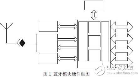
BlueCore2 chip introduction
The Bluetooth module uses the BlueCore2-External (BC212015) chip, which is a single-chip Bluetooth chip from the British CSR company that integrates baseband and RF in the 2.4GHz ISM (Industrial, Scientific, Medical) band.
The internal structure of the BlueCore2-External chip is shown in Figure 1. The chip integrates 32Kbytes of on-chip RAM, DSP, MCU, RF front-end and various I/O ports. Various I/O ports include SPI, UART, USB, PIO, PCM, I2C and other interfaces. The SPI, UART, and USB interfaces are mainly used to transfer data; the I2C bus is used to link EEPROM; the PIO interface is a programmable interface; the PCM interface is used to transmit voice; and the maximum transmission rate of the UART interface in BlueCore2 is 1.5 Mbps. The 723.2 kbps data transfer rate specified in the Bluetooth standard.
Storage circuit
Since the Bluetooth chip does not come with a protocol stack, a flash is needed to store the protocol stack and application software. One of the SST39VF series from Silicon Storage Technology (SST) was selected for this design. The flash memory model is SST39VF800. The SST39VF800 is a successful example of SST's multi-purpose high-precision CMOS flash technology. It uses component design of discrete gates and oxidized channel injection technology to improve storage reliability and process and performance far superior to other competitors. In addition, SST has optimized the performance of the SST39VF800 for portable devices, making it less energy in operation, faster program execution, and more suitable for portable devices. According to the size of the Bluetooth protocol stack, 8Mbit SST39VF800 is used, the reading time is 70ns, and the working voltage is 2.7~3.6V. In order to meet the demanding requirements of the industrial site, the model supporting the industrial temperature range of -20°C~+85°C is selected.
Bandpass filter + balun (Balun)
Usually the RF transmitter outputs two differential signals, TX[_]A and TX[_]B, whose output characteristics are balanced (symmetric). The cable output from the antenna is a 50 ohm unbalanced coaxial cable. When the coaxial cable is directly connected to the balanced system, the coaxial cable has not only a high-frequency current inside the shield layer, but also a high-frequency current flow outside the shield layer. This will cause unnecessary coupling, causing a lot of interference, and even the surrounding equipment will not work properly. Therefore, it is necessary to connect a balun between the antenna and the transmitter output. The bandpass filter is typically a passive device that filters out signals in bands that are not required by the receiver, and provides selective signals to the low noise amplifier (LNA) to reduce interference. In this design, the ACX company's integrated bandpass filter + balun device FB2520 is used. The bandpass filter and the balun are integrated to achieve higher integration and effective reduction of the board. The area has the advantages of small size and low insertion loss, which can complete the balance to unbalanced end conversion and band pass filtering.
Power module Bluetooth module required
The 3.3V and 1.8V voltages, 1.8V for the Bluetooth chip and bandpass filter + balun, 3.3V is to provide voltage for the FLASH chip and the peripheral I / O pin of the Bluetooth chip. Since the voltage introduced from the master device is 3.3V, a DC-DC chip is required to implement voltage conversion on the Bluetooth module. In this design, the XC6204B182MR high-speed LDO conversion chip widely used in mobile phones is used for 3.3V to 1.8V voltage conversion. The maximum output current of the chip is 150mA, and the output voltage range is 1.8V-6V, which fully meets the power requirements of the Bluetooth module.
Crystal oscillator CSX-5032
The crystal oscillator selected is the CSX-5032 which is a chip crystal unit made of lead-free surface. The high-reliability ceramic hermetic package ensures high-frequency stability and excellent solderability in a wide range of applications such as PHS, GPS handsets, Bluetooth, and WLAN. We chose a 16MHz model with a size of 5mmX3.2mm, a frequency tolerance of +10ppm at 25°C and a frequency stability of +-5ppm.
Bluetooth module software design
The software design of the Bluetooth module is divided into two parts: protocol layer loading and module initial parameter setting. The Bluetooth protocol provides a complete solution for multiple applications built on top of Bluetooth technology, but for different applications, only a few of the Bluetooth protocols are used, and for each part of the protocol, all the functions it provides are not necessary. .
Protocol layer loading
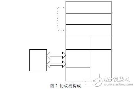
As shown in Figure 2, since this module is mainly used for industrial wireless communication, only the baseband (including LC), LM and HCI (Host Control Interface) protocol layers are loaded in the external Flash of the module. The HCI provides a command interface for the baseband controller and link manager in the Bluetooth hardware to enable access to the hardware status register and control registers, in particular the interface provides a unified access mode to the Bluetooth baseband. Loading these protocol layer modules implements complete Bluetooth link control and embedded HCI protocol, shielding the two hardware protocol layers of RF and baseband, and future application development can start directly from the HCI layer. By encapsulating the HCI protocol layer, standard HCI interface functions can be generated to provide a complete platform for upper-layer application development.
When the external host has a UART or USB interface and the Bluetooth module is compatible with the host signal level, there is no need to add other auxiliary circuits, and the Bluetooth module can be directly connected to the host.
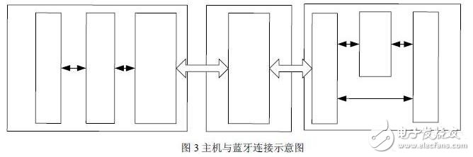
Figure 3 shows the connection between the host and the Bluetooth hardware. The Host Controller Interface (HCI) provides a common interface for accessing Bluetooth hardware capabilities. The HCI layer implements HCI commands for Bluetooth hardware by accessing baseband commands, link manager commands, hardware status registers, control registers, and event registers. Several intermediate layers between the host system's HCI driver and Bluetooth's hardware HCI firmware, also known as the host controller transport layer, provide the ability to transfer data. The target of this layer is transparent. The host controller driver does not care whether it is on the UART or USB. The data sent by the UART and USB to the host controller driver to the host controller cannot be processed, so the host controller interface and The host controller can be upgraded and the upgrade will have no effect on the transport layer.
Module initial parameter setting
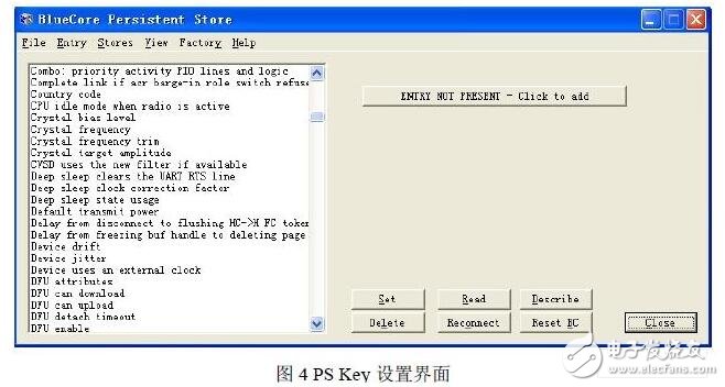
The Bluetooth module does not work after loading various protocol layers. It also needs to set the initial parameters of the module according to different hardware designs. The initial parameter setting based on the bluecore2 Bluetooth chip is also called PSK setting, which can be realized by BLUELAB integrated development environment or PS Key setting software. As shown in the figure, the interface is set for ps key.
Bluetooth module application example
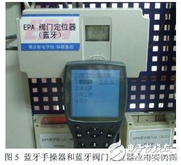
As shown in Figure 4, the Bluetooth Communicator and the Bluetooth Valve Positioner are used as examples. The Bluetooth module and the control panel in the valve positioner perform serial port (UART) full-duplex communication, and various parameters such as valve position value and valve position upper limit of the valve positioner are sent to the Bluetooth module through the serial port, and are transmitted to the Bluetooth module through Bluetooth wireless communication. Bluetooth Communicator, the Communicator can dynamically modify the corresponding parameters of the valve positioner with relevant instructions, which changes the traditional parameter setting or modification method. The Bluetooth module in the valve positioner is set to the passive link mode. After the device is started, the valve positioner periodically collects the valve position value and stores it in the buffer of the device. When the Bluetooth handheld device searches for the valve positioner, The valve positioner sends a link command, and after the link is established, the Bluetooth Communicator will get a link handle. After that, the monitoring interface shown in Figure 5 is entered, and the functions of reading the valve position value, the valve position upper limit, and the writing upper limit can be performed. Each function is executed by the Communicator to send a control command, which is sent by the serial port to the Bluetooth module, including the Bluetooth link handle, function code (0x01-0x03 for the above three functions) and CRC check area. After receiving the control command, the valve positioner first determines the link handle, determines whether to receive the instruction, and then executes the corresponding task according to the function code. Figure 5 shows the valve position values ​​of the valve positioner read by the Bluetooth Communicator. In addition, the Bluetooth Communicator can also operate devices such as Bluetooth electromagnetic flowmeters and Bluetooth temperature transmitters.
in conclusion
The field test shows that the Bluetooth module designed in this paper has stable performance, convenient use, strong practicability, certain anti-interference ability, software upgrade according to needs, and can be effectively embedded in the field device instead of cable for wireless communication. The extension of the traditional wired industrial control bus provides a new networking method for industrial monitoring networks.
The Bluetooth wireless communication module is designed using BlueCore2-External Bluetooth chip, FB2520 bandpass filter and balun, LTCC ceramic antenna, etc., and is actually used in Bluetooth Communicator and valve positioner. The result shows that the Bluetooth The module has stable performance and strong practicability.
Roll Forming Machine
Roll Forming Machine consists of feeding, molding and cutting board after color production appearance tidy and beautiful, high strength, durable, widely used in industrial and civil buildings, such as factories, warehouses, stadiums, exhibition halls, theaters room surface and wall.
Its components including roll forming parts,PLC, computer control system, hydraulic pump station system, automatic cutting system.
Roll Forming Machine must use high pulse input function, high input of excellent performance, choose AB phase interference ability. And by setting interrupt function, ensure accuracy.
Our company is the most powerful manufacturer in cold roll forming machinery in China.
Symple Specification need offered.
1 Coil Width:
2 Cover Width:
3 Rolling Speed:
4 Rolling Thickness:
5Machine Dimension(LXWXH):
There are some popular types of Roll Forming Machine:
1 Corrugated Roofing Roll Forming Machine
2 Glazed Tile Roll Forming Machine
3 Ridge Cap Roll Forming Machine
4 Roof And Wall Panel Roll Forming Machine
5 CZ Purlin Roll Forming Machine
6 Trapezoidal Sheet Roll Forming Machine
7 Light Steel Keel Roll Forming Machine
8 Floor Deck Roll Forming Machine
9 Sandwich Panel Roll Forming Machine
10 Double Deck Roll Forming Machine
Our product was passed strict quality inspection. We have testing department to make sure quality of machine are trustworthy. The quality of the Roll Forming Machine is very reliable.
If you have any questions, please contact with us directly, and welcome to visit our factory.
Roll Forming Machine,Cold Roll Forming Machine,Roll Forming Machine Design,Sheet Metal Roll Forming Machines
HEBEI HANMAC MACHINE CO., LTD. , https://www.chinahanmac.com