![<?echo $_SERVER['SERVER_NAME'];?>](/template/twentyseventeen/skin/images/header.jpg)
10 years ago, the Nokia smart phone or MTK function machine, the battery of about 1000mAh is enough to ensure the use of these phones for more than one day. The 300-500mA charging current is enough to allow these phones to charge at a reasonable speed. The standard USB power supply or dedicated line charger has been able to meet the needs of these mobile phone charging.
Five years ago, the Windows Mobile smartphone and the early Android smartphone increased battery capacity to around 1500mAh. At this time, the USB BC1.1 protocol appeared, providing DCP (dedicated charging port mode) to identify and distinguish the charger by using the USB data pin, thereby extending the standard USB port's 500mA current to 1.5A, which satisfies these devices. The charging needs.
The times are changing, and the power consumption of large-screen smartphones has reached a new height. People's dependence on mobile phones is far more than 10 years ago. Today, mobile phones have become a tool for people to communicate with the world (including but not limited to the Internet, calls), and to communicate with their own hearts (including games, etc.). The time ratio of actual use of mobile phones has greatly increased. This puts extremely high demands on the energy of the mobile phone battery. At the same time, the design of the mobile phone tends to be light and thin, and does not support the rapid replacement of the battery. The energy input is completely dependent on the charging and data ports.
However, the size of the charging port of the mobile phone has not increased, but has been moving toward miniaturization. The reduction in the electrical contact area of ​​the port is accompanied by an increase in contact resistance and a decrease in heat dissipation capability, which causes the current that the port can pass to decrease.
Input power of the port = input voltage x input current. It can be seen that the contradiction between the decrease of the port current capacity and the increase of the port input power can be solved by increasing the port input voltage. This is the original intention of the Qualcomm QC2.0/3.0 HVDCP (high voltage dedicated charging port). It is worth mentioning that USB 3.1 PD and MTK PUMPEXPRESS PLUS also use the same solution.
Analysis of the principle <br> Before talking about the hardware implementation of QC fast charge, I would like to mention the comments I have seen on the Internet about QC fast charge. There are many articles that have such a statement: the high voltage charging used by QC is harmful to mobile phone batteries. In my opinion, this statement exists because of the lack of understanding of how the circuit inside the phone completes the battery charging process. Therefore, the following section not only describes how QC is implemented by hardware, but also how other phones complete battery charging.
The battery charging circuit in the mobile phone can be divided into two parts according to the function (but it does not mean that the two parts are physically separated). In fact, the two circuits are often implemented in the same integrated circuit.
1. Measurement-feedback control part <br> Responsible for monitoring key parameters of battery charging (such as battery charging current, current battery voltage, battery temperature), adjusting parameters such as charging current according to preset battery charging algorithm, or off Discharged. In the measurement and feedback control part of the mobile phone charging circuit, certain parameters can usually be adjusted through software programming. Even some of the functions of the measurement and feedback control of mobile phone charging are done by software. Most cell phone control algorithms for charging lithium batteries are based on constant current - constant voltage processes or variants thereof. The process of constant current and constant voltage charging is basically the same. First, when the battery is lower than its charging limit voltage (the previous mobile phone is 4.2v, now 4.35V is common, or 4.40V is occasionally), the battery is charged at a constant current.
The ratio of the magnitude of this constant current to the battery capacity (called the charge current override) is closely related to the battery charging speed of the mobile phone. To increase the charging speed of the mobile phone, it is an effective means to increase the charging current multiplier. However, the mobile phone battery has limited ability to accept the charging current multiplier. Excessive charging current multiplier will cause the cycle attenuation of the mobile phone battery to increase, and may even cause battery safety problems. At present, most mobile phone batteries can accept a charging current ratio of 0.5-1 times. For example, for a 3000mAh mobile phone battery, a charging current ratio of 0.5-1 times corresponds to a charging current of 1500 mA-3000 mA. By optimizing the battery structure and formulation, the battery can accept a larger charge current rate. As far as the current situation is concerned, the upper limit of the charging current rate of the mobile phone battery is usually not the bottleneck of the charging speed of the mobile phone.
After the battery reaches the charge limit voltage of the battery by constant current charging, the charge limit voltage is maintained by gradually decreasing the charge current. Because the lithium-ion battery voltage rises in addition to the increase in battery fullness, the higher the charging current, the higher the battery voltage. Therefore, when the fullness is increasing, reducing the charging current can keep the battery voltage constant. Constant pressure process. When the charging current is reduced to a predetermined value, the charging current is turned off and charging is completed.
2. Voltage and current conversion part <br> The function of this part of the circuit is to convert the electric energy obtained from the charging port of the mobile phone into the charging current of the battery under the control of the measurement and feedback control part. Since the voltage input to the charging port of the mobile phone is usually 5V, 9V, etc., it does not match the battery voltage (3.0V-4.35V, which varies with the power and charging current), so it needs to be changed. It is because of this transformation process that high voltage charging affects battery life is ridiculous. Because the mobile phone battery charging voltage and current are determined by the measurement and feedback control part of the preset charging procedure. The input voltage is a little higher or lower, and as long as it is within the range allowed by the voltage-current conversion section, it is converted into a programmed value by the voltage-current conversion section.
There are three types of voltage and current conversion circuits:
(1) Linear conversion circuit.
The essence is a variable resistor controlled by the measurement and feedback control part. The part of the charger voltage higher than the battery voltage is consumed by the resistor and is consumed by the heat generation. For example, when the voltage input to the charging port is 5V, the battery voltage is 3.7V, and a charging current of 1000mA is required. Then let the resistance of the variable resistor be just 1.3Ω. As long as the resistance of this variable resistor can be constantly changed, the entire process of constant current and constant voltage can be completed. According to Kirchhoff's law, the input current of this circuit is equal to the output current. Therefore, increasing the input voltage for this circuit will only dissipate more input power through the resistor without increasing the battery's charging power. In addition, the heating power of this circuit is (input voltage - battery voltage) × charging current. When the charging current is large, the heating power is also large. Therefore, this circuit is not suitable for charging mobile phones that require high current charging and limited space. This is also the reason why high-voltage fast-charge and large-scale heating, some mobile phone manufacturers began to use low-voltage and high-current fast charge.
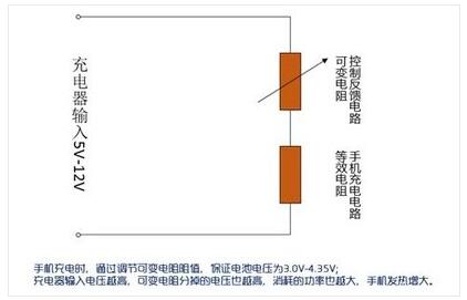
Linear conversion circuit
(2) Switching conversion circuit.
The structure of this circuit is shown below. S1 (usually implemented by MOSFETs) and inductors are used to reduce the input voltage to the battery voltage. The charging current is controlled under the control of the measurement and feedback control. The relationship between the output current and voltage of this circuit and the input current and voltage can be obtained by the law of conservation of energy: input voltage × input current × efficiency = output voltage × output current. In the new mobile phone, this efficiency can reach more than 90%. It is with this switching circuit that QC2.0 can convert the input high voltage and small current into battery voltage and large charging current.
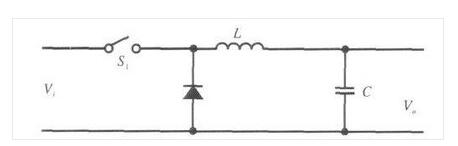
Switching conversion circuit
For example: the battery voltage is 3.7V. A 2A battery charging current is required. The charging circuit is 90% efficient, ignoring the voltage drop caused by other resistors. When the input port voltage is 9.0V, the current through the input port needs to be: 3.7V*2.0A/90%/9.0V=0.91A. It can be seen that the QC fast charge can effectively reduce the current of the input port by increasing the input voltage.
(3) Designing the constant current circuit in a dedicated charger This circuit can be found in some early PHS and Motorola models. Oppo's VOOC ultrafast charging may also use this design. The principle is to place the constant current circuit in a dedicated constant current charger instead of the mobile phone. There are only electronic switches (MOSFETs) in the mobile phone that control the circuit. When the switch is turned on, the charger is directly connected to the battery, relying on the circuit in the charger to regulate the output voltage and control the charging current. Of course, the function of full charge stop is completed by the electronic circuit control of the internal circuit of the mobile phone. The advantage of this is that the circuit inside the mobile phone is relatively simple, and it is not necessary to generate excessive voltage in the internal heat of the mobile phone. The disadvantage is that a dedicated charger is required. (When the MOTO adopts this design, if it uses a USB charger with a large current, it will burn out the internal electronic switch and cause the phone to malfunction.)
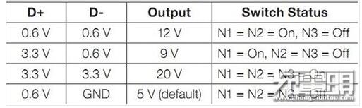
3, Qualcomm QC handshake protocol QC fast charge charger and mobile phone through the micro USB interface between the two lines (D + D-) load voltage to communicate, adjust the QC output voltage. The handshake process is as follows: When the charger terminal is connected to the mobile phone through the data line, the charger defaults to D+D- short circuit through MOS, and the mobile phone terminal detects that the charger type is DCP (dedicated charging port mode). At this time, the output voltage is 5V, and the mobile phone is normally charged. If the phone supports the QC2.0 fast charging protocol, the hvdcp process of the Android user space will start and start loading 0.325V on D+. When this voltage is maintained for 1.25s, the charger will disconnect D+ and D-, and the voltage on D- will decrease. After the mobile terminal detects the voltage drop on D-, hvdcp reads /sys/class/ The value of power_supply/usb/voltage_max, if it is 9000000 (mV), set the voltage on D+ to 3.3V, the voltage on D- to 0.6V, and the charger to output 9v. If 5000000 (mV) is set D+ is 0.6V, D- is 0V, and the charger outputs 5V voltage.
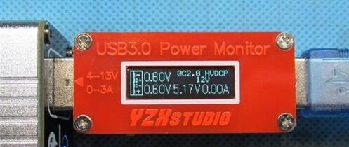
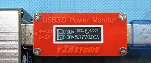
4, QC charging combat <br> Here we are using a USB meter to visually test the QC2.0 charger voltage identification change process. Inserting the USB interface can detect the D+ D- voltage used to detect the QC2.0 signal, and also display the voltage and current of the input and output. Built-in coulomb counter with precision up to the multimeter level.
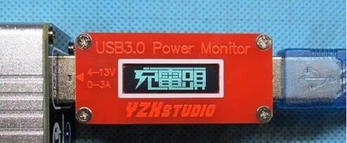
Power on, plug in the phone: DCP mode, but there is a pull-down resistor, so the voltage is relatively low, but the two voltages are basically the same.
Power on, DCP mode before plugging in the phone
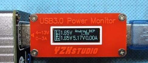
The moment the phone is plugged in, the phone will add a detection voltage of 0.6V to D+, because the D-D-short is also high.
Insert the phone for a moment
After the application voltage on D+ is maintained for more than 1.25 seconds, the charger will disconnect the short circuit of D+ and D-, D- becomes 0, and D+ is still the identification voltage given by the mobile phone.
D+, D- disconnect
The mobile phone detects that D- becomes 0, indicating that the charger supports QC2.0 and sends an application to change the voltage.

D- becomes 0, the voltage rises
As for how much voltage the charger outputs to the phone, see this table. It should be noted that all 0.6V stands for 0.325-2.000V, and all 3.3V stands for more than 2.000V. Within this range, the QC2.0 handshake protocol can be applied correctly.
Rechargeable Battery & Charger
Battery
Zhejiang Baishili Battery Technology Service Co,.Ltd. , http://www.bslbatteryservice.com