![<?echo $_SERVER['SERVER_NAME'];?>](/template/twentyseventeen/skin/images/header.jpg)
The usual current sensors and transformers convert large currents into small currents of the same frequency in phase to facilitate measurement or isolation. According to different transformation principles, there are generally current sensors/transformers based on the principles of electromagnetic induction, Hall effect, and fluxgate. This article will introduce how to use the right sensor at the scene to ensure the best test results.
Due to the sensor's "dead zone" measurement problem, the large-range sensor cannot test small currents, so the test site often needs to select a variety of sensors to match different test occasions. So how do you choose? We introduce them one by one.
First, the current transformer
A current transformer is similar to a transformer with a small number of primary turns and a large number of secondary turns. Ideally, the ratio of the primary and secondary currents is inversely proportional to the turns ratio. The current conversion ratio is marked with the primary and secondary rated currents, for example, "300A/5A", indicating that the measured current is 5A when the rated current is 300A. Since the primary and secondary coils have leakage inductance and resistance, and the excitation current and the core magnetization curve are nonlinear, the transformer produces a ratio error and a phase error. The accuracy of the transformer used for metering and charging is generally 0.1~1. It can be known from the principle of transformers that it can not measure DC current. It is usually designed for power frequency measurement. The accuracy is the parameter under power frequency. The bandwidth is narrow. It is not suitable for harmonic analysis and non-sinusoidal measurement. If the measured signal Containing a lot of harmonics, the result is very serious. Use current transformers must be careful not to open the secondary, otherwise high voltage will endanger the safety of people and equipment.
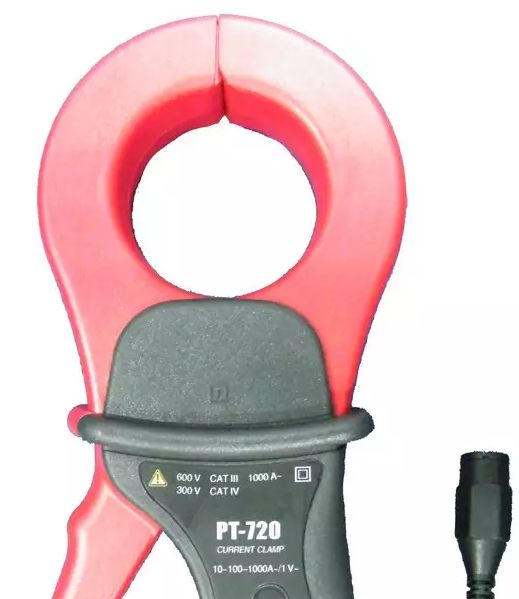
Second, the current clamp
Current clamps are arguably the most widely used sensors, they are small, flexible, and can be adapted to almost all test situations. In principle, it is mainly divided into two types: electromagnetic induction principle and Hall effect.
The current clamp based on the principle of electromagnetic induction is the same as the transformer. The core is divided into two parts. When closed, the two cores need to be tightly combined. Some current clamps are connected to the resistor output as a voltage signal, and the output without internal resistance is a current signal. This is also why some manufacturers of the same type of current clamp have two types of current and voltage output, the most typical is the C117 and C116 of French CA. Due to the degree of closure of the two cores, the current clamp accuracy is usually worse than the transformer. Similarly, current clamps based on electromagnetic induction can only measure AC.
The Hall effect-based current clamp is an air gap placed in the iron core to place the Hall element, and the Hall element is used to measure the magnetic induction intensity in the air gap. According to different control methods, there are two types of open loop and closed loop. The open-loop Hall type uses a Hall element with better linearity, and the output voltage of the Hall element is proportional to the current to be measured. The closed-loop Hall type uses zero-flux technology with a compensation coil on the core. When the primary current has a measured magnetic flux in the iron core, the Hall element detects the magnetic induction intensity in the iron core, and converts the error voltage into a current-driven compensation coil through negative feedback, canceling the magnetic flux in the iron core, and finally being The current measured is opposite to the magnitude of the magnetic flux generated by the compensation coil. By measuring the current of the compensation coil, the measured current can be converted according to the turns ratio.
Both open-loop and closed-loop Hall-type current clamps can measure DC and AC. The open-loop Hall is affected by the nonlinearity of the core and the temperature characteristics of the Hall element, and the accuracy and linearity are poor, but the cost is low. The closed-loop Hall has less dependence on the linearity of the Hall element, and the core operates under zero flux, so the accuracy is higher than that of the open loop. However, the current clamp has a problem that the movable iron core is not ideally closed, and it is almost equal to better than 0.1%. It can be achieved that 1% is already a very high index. The Hall element needs to provide the operating voltage, so both current clamps must be powered, and the closed-loop Hall needs to drive the compensation coil to consume more power.
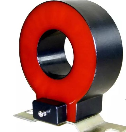
Third, closed current sensor
Usually, like the Hall-type current clamp, there are two types of open-loop and closed-loop Hall, and the output is a current or voltage signal. Due to the closed form, which is more accurate than the same type of current clamp, most of our most common LEM LF series sensors are this principle.

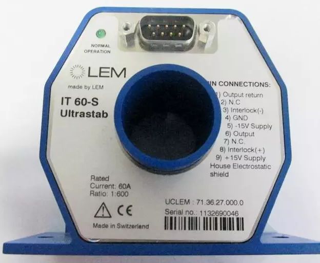
In addition, current sensors using fluxgate technology have an accuracy of better than 0.05% or even 12 ppm, but this type of sensor is very expensive and fragile. In the event that the sensor is not powered during use, the current being measured will cause damage to the sensor. The most common of these sensors is the LEM IT series of sensors.
Fourth, precision resistors
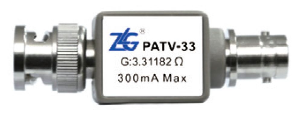
Precision resistors can be said to be often overlooked. Maybe you don't know where to use it. Its essence is actually a resistor, which can convert the current signal into a voltage signal. When is it used? Use an example to illustrate.
When using the power meter PA333H and LEM LF 205-S sensor for testing, the ratio of the sensor is 1:2000, the minimum current that the power meter PA333H can accurately test is 10mA. After conversion, the minimum current that can be measured by the sensor is 20A! This combination is obviously unreasonable, but there are still many occasions that need to be used. What if I need to test the current below 20A? In addition to changing the converter to a smaller sensor and switching to a power analyzer (smaller current can be measured), a tight resistor can also be used. For example, Zhiyuan Electronics' PATV-33 has a resistance of about 3.3 ohms. After that, the ratio of this combination becomes 1.65mV/A, and the minimum can be measured to about 0.3A. The ability of the sensor to measure small currents is greatly improved.
V. Summary
Test equipment combined with Hall sensor test solutions have been applied in industrial production, automotive, new energy and other fields, the overall measurement accuracy is not only determined by the test equipment, the sensor also plays an indispensable role. In the test process, it is very necessary to select the appropriate sensor and use the correct measurement method, which will directly affect the overall test results.
The latest Windows has multiple versions, including Basic, Home, and Ultimate. Windows has developed from a simple GUI to a typical operating system with its own file format and drivers, and has actually become the most user-friendly operating system. Windows has added the Multiple Desktops feature. This function allows users to use multiple desktop environments under the same operating system, that is, users can switch between different desktop environments according to their needs. It can be said that on the tablet platform, the Windows operating system has a good foundation.
Windows Tablet,New Windows Tablet,Tablet Windows
Jingjiang Gisen Technology Co.,Ltd , https://www.jsgisengroup.com