![<?echo $_SERVER['SERVER_NAME'];?>](/template/twentyseventeen/skin/images/header.jpg)
Component selection should be an essential step for engineers when designing. Selecting the right inductor can help the RF receiver to process the signal more efficiently and better suppress more peak noise. When selecting the inductor, multiple parameters need to be considered comprehensively. So how do you choose the right RF inductor? This article will teach you how to choose RF inductors from six key aspects.
The choice of RF inductors involves such key parameters as: mounting method (surface-mount or in-line), inductance value, current rating, DC resistance (DCR), self-resonant frequency (SRF), quality factor and temperature rating . In applications, inductors generally pursue small dimensions, but the size of inductors in a given application is often limited by physical laws. The inductor value and current rating are the main determinants of its size, after which other parameters can be optimized.
The key to determine the inductance value of the factors
If the inductor is used as a simple single element (first stage) high frequency choke, it should be selected based on the peak noise frequency that needs to be controlled. At the self-resonant frequency (SRF) of the inductor, the series impedance will reach its maximum value. Therefore, to select a simple RF choke, an inductor with an SRF close to the required choke frequency should be found.
For high-order filters, the inductance of each element must be calculated based on the cutoff frequency (low-pass and high-pass filter) or bandwidth (pass filter) of the filter. Commercial circuit simulation software such as SPICE, AWR's MicrowaveOffice, and Agilent's Genesys or ADS are commonly used for these calculations.
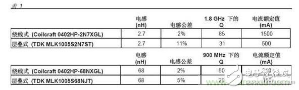
For tuning circuits or impedance matching, strict inductance tolerances are required. As shown in Table 1, wire wound inductors typically achieve tighter tolerances than stacked or thick film inductors.
The second key, current requirements determine the DC resistance
The current rating is closely related to the DCR. In most cases, if all other parameters remain equal, then a larger size product needs to be selected to reduce the DCR.
The third key is the self-resonant frequency that allows the inductor to operate
SRF's formula is:
In the application of chokes, SRF can block the signal frequency most effectively. At frequencies below SRF, the impedance increases with increasing frequency. In SRF, the impedance reaches a maximum. At frequencies above SRF, the impedance decreases with decreasing frequency.
For higher order filters or impedance matching applications, it is more important to have a smoother inductor curve (constant inductance vs. frequency) near the desired frequency. This requires the selection of an inductor whose SRF is much higher than the design frequency. Based on past experience, one can choose an inductor that is 10 times (10×) higher than the operating frequency. In general, the choice of inductance value usually determines the SRF, and vice versa. As the winding capacitance increases, the higher the inductance, the lower the SRF. Key Four: Inductance and Impedance vs. Frequency
As shown in Figure 1, the inductance and impedance rise sharply as they approach the self-resonant frequency (SRF) of the inductor. For choke applications, choose an inductor with an SRF equal to or near the attenuation frequency. For other applications, the SRF should be at least 10 times higher than the operating frequency.
Key Four: When is the value of Q important?
High Q values ​​produce a narrow bandwidth, which is very important for applications where the inductor is used for LC (oscillation) loops or narrow bandpass. Please refer to Figure 2. High Q values ​​also produce low insertion loss, which minimizes power loss.
The formula for calculating the inductor Q is:
All frequency-dependent real and imaginary losses are included in the calculation of Q, including inductance, capacitance, the skin effect of the conductor, and the core loss of the magnetic material. As shown in Table 1, the wound inductor has a much higher Q than a stacked inductor of the same size and inductance.
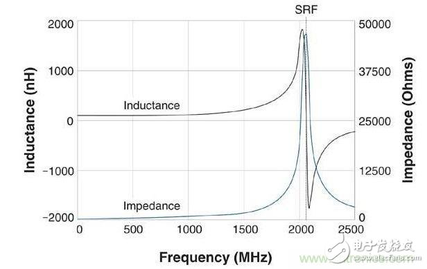
Figure 1: Inductance and Impedance of a 100nH Wirewound Inductor
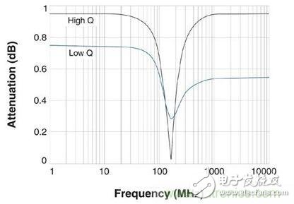
Figure 2: High-Q produces narrow bandwidth and
The key five, how to choose the temperature rating
The power loss increases with the increase of current and DC resistance, resulting in an increase in the temperature of the element. Inductors are typically rated for a particular ambient temperature and temperature rise above ambient temperature due to current flowing through the inductor. For example, a component is rated at an ambient temperature of 125°C and a temperature rise of 15°C due to full load rated current (Irms or Idc). Its maximum temperature is about 140°C. You just need to confirm that your application's ambient temperature and current consumption do not exceed the inductor's rating.
Middle-low Level Lighting Sky Curtain
Middle-Low Level Lighting Sky Curtain,Ultra Transparency Display,Digital Signage Video Display,High Brightness Led Outdoor Lighting
Kindwin Technology (H.K.) Limited , https://www.szktlled.com