![<?echo $_SERVER['SERVER_NAME'];?>](/template/twentyseventeen/skin/images/header.jpg)
When engineers draw PCBs, they will inevitably encounter some connected devices. In China, for a number of reasons, it is very difficult for these connecting devices to be able to request mechanical size documents from manufacturers as they have abroad. Therefore, in many cases, it is necessary to hold a vernier caliper. To measure. This results in that, once we do not know the pin connections of the connector, it is easy to connect the error; Second, there are always errors in the measurement of the connector itself, and the PCB connector drawn finally does not go up. Whether or not the standardization of connectors is standard or not, I think this is one of the gaps between China and foreign countries. Not only on the chip, but we do not do well in these details.
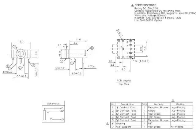
Headphone socket size
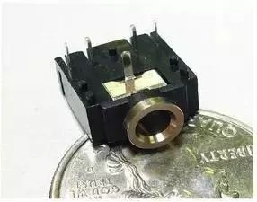
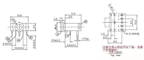
This is a 3.5mm stereo headphone jack we bought on the electronics market. Its mechanical dimensions are as follows:
There will be 12345 numbers next to the pins on the underside of the earphone socket, corresponding to the dimension drawings.
In general, the headset uses a 3-stage plug, the plug diameter is generally 3.5mm and 2.5mm, different diameters of the plug corresponding to different diameter hole headphone jack, so "public" and "mother" to correspond.
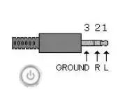
According to the connection of the three-stage headphone plug, the connection of the headphone jack can be determined:
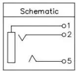
Pin 1 is grounded, 2 feet are connected to the right channel (Right), and 5 feet are connected to the left channel (Left). When the headphone connector is not plugged into the socket, pins 2 and 3, pins 4 and 5 are connected, and once the connector is plugged into the socket, pins 2 and 3, pins 4 and 5 are separated. Therefore, from the perspective of system reliability, pins 3 and 4 should be grounded. In this case, when the headphones are not plugged in, the left and right channels are grounded and the system input is 0. In many cases, we will use the 3 feet and 4 feet that aren't used, and then the feet 2 and 5 will be left unconnected. This poses the risk that if a large current is strung from the outside world, it will be transmitted from feet 2 and 5. On the board, it will burn the chip.
The headphone socket size chart: (Click to enlarge)
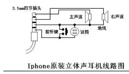
In addition to the three-stage headphone connector, there are four-stage, four-stage type more than a three-stage plus a microphone / answer button, the national standard (most mobile phones) from beginning to end (the tail is the cable side) is defined : Left channel, right channel, MIC, ground. It should be noted that the sequence of the iphone's four-segment headphone connector is not the same, from the head (tip) to the tail is the left channel, right channel, ground, MIC.

General mobile stereo headset connector
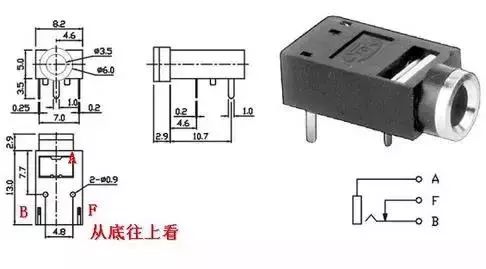
Mono headset socket
A mono headset jack can also be used as input. Note that A is ground, B should be connected to the input, and F should be grounded. When no headphone connector is connected, the B pin and F pin are connected together. This ensures that the input is grounded and the input signal is zero. When the headphone connector is connected, the B pin and the F pin are separated, and the F pin and A are connected together.
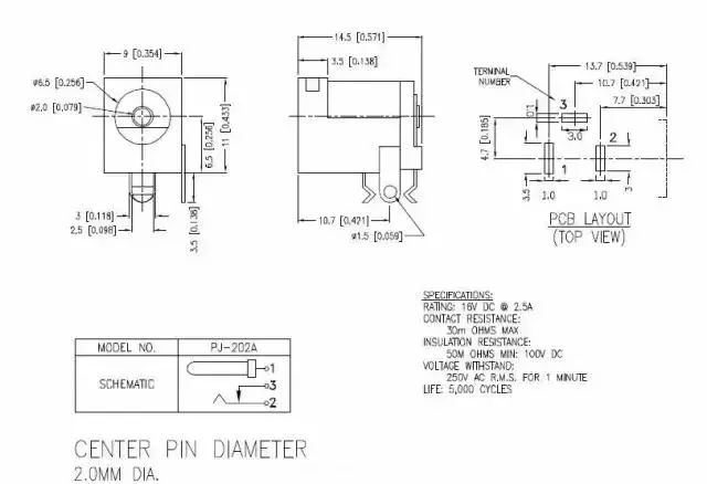
DC power input socket size
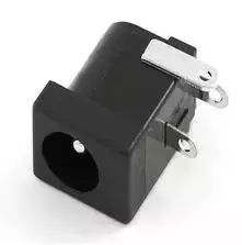
This is the DC power input socket that we usually use. Sizes are as follows: (Click to enlarge)
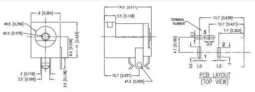
This DC power socket is a plug with an inside diameter of 2.1mm and an outside diameter of 5.5.
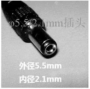
Outside diameter 5.5mm, inside diameter 2.1mm, length about 10mm

Power polarity: positive and negative
It should be noted that the plug is generally positive and negative, but it is not ruled out that a few plugs made by oneself are contradictory. Therefore, it is better to use a multimeter before use to avoid burning the chip.
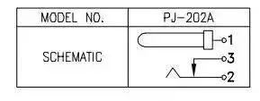
DC power socket wiring
The 2 feet and 3 feet of the DC power socket are connected together when the plug is not inserted. When the plug is inserted, the 3 feet are separated from the 2 feet. So 3 feet and 1 foot should be connected to the ground.
This DC power input socket size map: (Click to enlarge)
USB interface socket pin
USB is the abbreviation of Universal Serial Bus in English and Chinese means "universal serial bus".
USB version:
The first generation: USB 1.0/1.1 has a maximum transmission rate of 12 Mbps. Introduced in 1996.
Second generation: The maximum transfer rate of USB 2.0 is up to 480Mbps. USB 1.0/1.1 and USB 2.0 interfaces are compatible with each other.
Third generation: USB 3.0 maximum transfer rate 5Gbps, backward compatible with USB 1.0/1.1/2.0
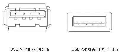
When drawing a PCB, you must know the USB pinout. The following is a front view of a socket or plug, that is, the socket or plug faces itself.
The USB-A socket is used on the host, and the USB-B socket is used on the peripheral.
USB Type A sockets and plugs:
USB type B socket and plug:
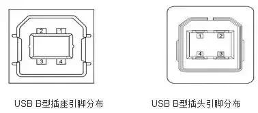
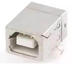
USB-B socket is used on peripherals
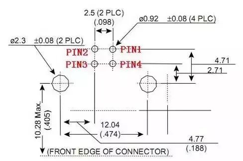
Dimensional drawing of this USB Type B Female Socket: (Click to enlarge)
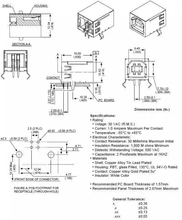
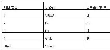
USB AB type pin function:
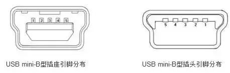
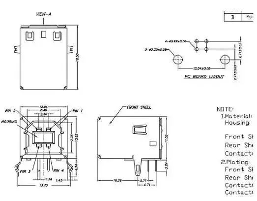
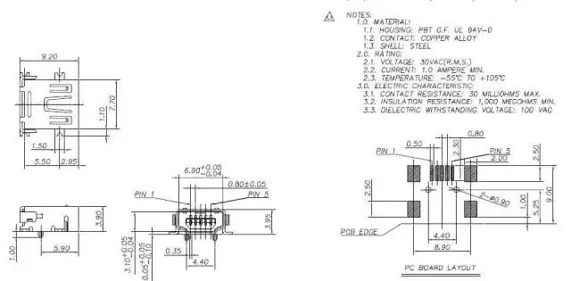
USB mini-B sockets and plugs:
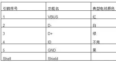
USB mini-B type pin function:
For the mechanical dimensions of the socket plug, please refer to the typical mechanical dimensions of the USB standard. The more reliable is the size of the connector manufacturer.
USB A-type socket DIP:
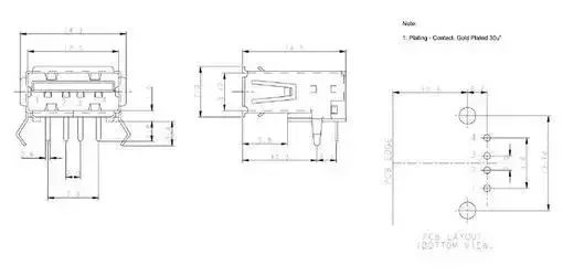
USB A type socket SMT patch:
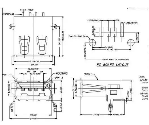
USB B type socket DIP line:
USB Mini-B socket patch:
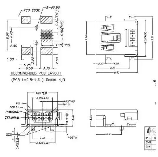
Painted USB Mini-B Protel package library
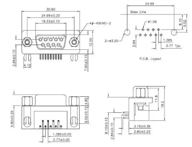
DB9 female serial port socket

We often use such a DB9 serial female socket on the development board. Its dimensions are as follows:
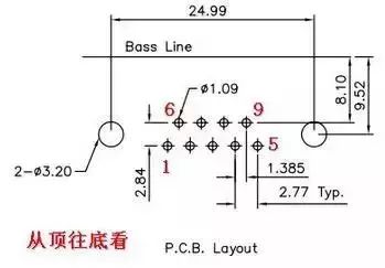
Look carefully at the numeric designation of the DB9 female surface.
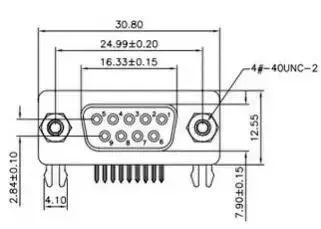
Usually the number of the female port should match the number of the male connector on the serial port.
A male (pin) is generally placed on a PCB of a main device (for example, a computer), and a female (hole) is generally placed on a device (such as a development board). The advantage of doing so is to reduce the number of joint damage to the main device, after all, the male is much stronger than the female.
Serial port connecting two devices to use the serial line, due to the diversity of many devices, so the serial line male-female, male and female, mother and mother of the serial line has, here we should pay attention to the serial port of the 2,3 pin connection, take The communication between the computer and the one-chip computer is taken as an example, if RS232 wants to communicate with, PC_RXD connects MCU_TXD, PC_TXD connects MCU_RXD. Both straight-through and cross-connected serial lines have the same connection relationship.
Basically, there is no indication on the serial line that pin 2 and pin 3 are connected directly or crosswise. Therefore, it is a good practice to use a serial line on the serial port that has been used later to indicate a directly connected or cross-over tag, so as to avoid each time. Use the serial cable to catch the flaw, and finally the serial port is not connected.
The dimension drawing of the DB9 female serial port:
SD card socket size chart
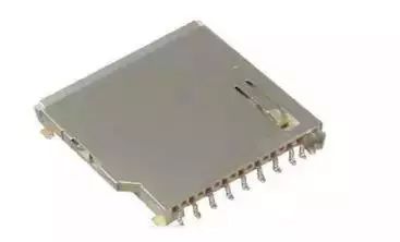
The figure above is an SD card holder that we generally buy in the electronics market. Its appearance dimensions are as follows:
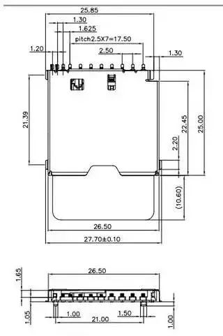
The PCB dimensions are as follows:
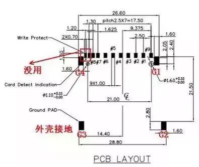
The two feet next to the 8-pin are useless, while the G1, G2, G3, and G4 are fixed feet. These four legs are also connected to the metal housing of the SD card holder. It is better to ground the card because of the SD card. To insert or pull it by hand, it is inevitable that static electricity will be carried to the card holder. If these fixed pins are connected to the ground, static electricity will be returned to the ground through these feet, but not to other functional pins. damage.
SD card size chart:
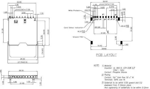
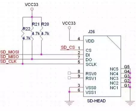
SD card wiring diagram (G5 is the two unused pins next to the 8-pin)
For Iphone:
For Iphone8/X/XR/XS Max
Compabile Models:
For Samsung:
For Galaxy S6, For Galaxy S6 Edge, For Galaxy S6 Edge+,
For Galaxy S6 Active, For Galaxy S6 Duos, For Galaxy Note Edge,
For Galaxy S7, For Galaxy S7 Edge, For Galaxy Note 5
For Galaxy S8, For Galaxy S8 Plus, For Galaxy Note 8
For Galaxy S9,For Galaxy S9 Plus
For Sony:
For Xperia Z4V, For Xperia Z3V
For Google:
For Nexus 4, For Nexus 5, For Nexus 6, For Nexus 7
For MOTORALA:
For Moto Droid Turbo, For Moto Droid Turbo 2, For Moto Droid 5
For NOKIA:
For Lumia 920, For Lumia 928, For Nokia Lumia 93, For Lumia 950, For Lumia 950 XL, For Lumia 1020, For Nokia Lumia 1050, For Nokia Lumia 822, For Nokia Lumia 735
For HTC:
For HTC ONE MAX T6, For HTC Incredible 4G, For HTC ONE mini 2, For HTC Droid DNA
For LG:
For LG Nexus 4, For LG Nexus 5, For LG G Pro, For LG D1L, For LG LTE2
For Others:
For YotaPhone 2, For Elephone P9000
Guangzhou HangDeng Tech Co. Ltd , http://www.hangdengtech.com