![<?echo $_SERVER['SERVER_NAME'];?>](/template/twentyseventeen/skin/images/header.jpg)
Verification (VerificaTIon) is to test whether the design is consistent with its corresponding standards (industry standards or custom standards), and how much redundancy there is. Verification and debugging are the main uses of oscilloscopes.
When debugging with an oscilloscope, the main indicators we care about are:
Waveform capture rate-determines how quickly the instrument can detect a fault
Trigger system-determines how accurately the instrument can locate the fault
Analytical ability-Determine how much useful information the instrument can extract from the waveform.
When using an oscilloscope for verification, the indicators we are more concerned about are: signal fidelity-determines whether the collected samples can truly reflect the characteristics of the signal; sampling rate and memory depth-determines how fast a single capture can be And how many samples to grab for verification testing; analysis tools-determine the degree and accuracy of in-depth analysis.
Signal fidelity is a more complex issue, covering the oscilloscope's bandwidth, sampling rate, interpolation, jitter noise floor, noise floor, time measurement accuracy, probe system, and many other aspects. There are many discussions in the industry on this, and there are many related articles, so this article will not do detailed analysis, only emphasize the impact of the oscilloscope's frequency response on verification.
The frequency response is reflected as bandwidth and rise time on the oscilloscope specifications. The bandwidth characterizes the steady-state response capability of the oscilloscope, and the rise time is the transient response. Empirically, the product of bandwidth and rise time (10 to 90%) is a constant, and this constant is related to the oscilloscope's amplifier model. Such as the Gaussian response amplifier model, this constant is 0.35; while the high-performance oscilloscope amplifier model is more complicated, the constant will be between 0.4 and 0.55. Of course, from the user's perspective, this constant should be as small as possible: the smaller the constant, the faster the rise time of the oscilloscope under the same bandwidth (steady-state response), which means that the transient response is better; and In the case of the same rise time, the bandwidth required by an oscilloscope with a small product will be relatively low-and for an oscilloscope, the bandwidth and the price are proportional, which means that an oscilloscope with a small product is more cost-effective.
We verify that the test objects are generally pulse (non-sinusoidal) signals, such as communication signals, serial bus signals, high-speed pulse signals, modulated signals, etc., so the oscilloscope's transient response is more important than it is. Tektronix DPO oscilloscope can provide the fastest rise time under the same bandwidth, which is very helpful for transient signal testing.
On the other hand, different design structures of high-bandwidth oscilloscopes will also affect the accuracy, accuracy and speed of verification tests:
In recent years, the bandwidth of oscilloscopes has been increasing at a high speed. How to ensure the flatness of the amplitude response and the linearity of the phase response while increasing the bandwidth has become an important issue. Experienced engineers know that it is impossible to get the ideal flat amplitude response and linear phase response by starting with the hardware completely. Therefore, in the amplifier technology of high-performance oscilloscopes, major oscilloscope manufacturers are using DSP technology to increase bandwidth and optimize response. The use of DSP technology can indeed get more ideal amplitude and phase response, but it is not beneficial. The following figure is the response of the oscilloscope to the step signal. The blue is the full analog response, and the red is the response after DSP processing.
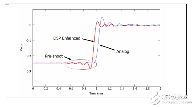
After the DSP improves, corrects the amplitude and phase response, the oscilloscope can more accurately measure the rise time, eye diagram redundancy and other indicators, which is beneficial to the verification test of digital communication signals and computer bus signals. But you can see from the red waveform: the part of the dotted frame, we call it "pre-overshoot", is a kind of "false waveform" that does not exist in the real signal, it is the distortion generated by the DSP processing-for the step signal In other words, there is no reason why the waveform starts to oscillate when the rising energy has not been generated. So when using an oscilloscope to measure high-speed pulses, laser pulses, or similar signals, DSP processing is no longer what testers expect—distorted waveform errors indicate physical behavior at various points in time.
Of course, there are other problems with DSP, such as the wrong display of overdriven signals, lower data throughput speed, and the inability to export the original data before DSP. Therefore, when users need to observe the overdrive signal (such as the overshoot details at the top of the pulse), need to use the original data collected by the oscilloscope for custom analysis (such as laser pulse measurement), or require a higher processing speed, the oscilloscope is not required to use DSP Features.
Tektronix uses DSP frequency response correction and channel matching in all DPOs above 2.5GHz bandwidth. DPO72004 also has DSP bandwidth enhancement. However, Tektronix is ​​also well aware of the pros and cons of DSP functions, so when other companies "quietly" use DSP functions, Tektronix only gives users the "right to know" and "control rights," that is, users can know whether the oscilloscope is using DSP functions. At the same time, DSP boost function can be turned on or off as needed. In this way, the user can choose to turn off the DSP function when performing a pulse test that requires the original acquisition data of the oscilloscope; while performing the serial signal conformance test, Tektronix recommends that the DSP function can be turned on.
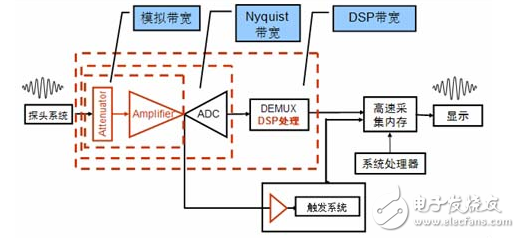
In addition to the need to pay attention to these matters in the application, there are some requirements for the DSP function. We can see from the above figure that DSP requirements must meet the Nyquist sampling rate for real-time sampling. Some manufacturers' oscilloscopes have unpredictable waveform amplitude distortion when the sampling rate does not meet the Nyquist bandwidth, mostly from this reason.
At the same time, high-performance oscilloscopes are generally 4 channels. But to achieve the calibration bandwidth on four channels at the same time, the sampling rate support is also required. It is generally accepted in the industry that a sampling rate of 2.5 times the bandwidth is the minimum requirement for guaranteed bandwidth. In this way, if an oscilloscope above 8GHz is used for signal verification (usually a single acquisition), Tektronix DPO can simultaneously provide full bandwidth performance on 4 channels at the same time (50G sampling rate per channel can effectively guarantee a bandwidth of up to 20GHz), The oscilloscope with shared amplifier and ADC structure can only reach the full bandwidth index on two channels at most, and some even only guarantee the performance of one channel.
In terms of storage depth, many verification tests require sufficient data. For example, in the process of jitter and eye diagram testing of high-speed serial signals, it is required to capture a large amount of data at a time for accurate jitter measurement and estimation, while ensuring a low bit error rate. To avoid the accidental and uncertain results of capturing a small amount of data for analysis. For example, the HDMI test specification (CTS1.2 a Page 15) requires the capture of 1 million bits of data for eye diagram analysis. It requires two channels of the oscilloscope to use a 16M memory depth at a sampling rate of 10Gs / S. FBD Sigtest (Release notes Page6) recommends capturing 1 million bits of data for eye diagram analysis. The PCIE 2.0 specification (Page239) stipulates that it is mandatory to capture 1Mlillion data for eye diagram jitter analysis. You need an oscilloscope single channel with a storage depth of 8M at a sampling rate of 40Gs / S.
Another example: In order to reduce the crosstalk and radiation of EMI, the spread spectrum clock is used in most high-speed serial signals, which can make the serial signal rate drift within an appropriate range. In order to spread its spectrum in a wide range, the peak value is significantly reduced, which can effectively reduce EMI problems. For example, the FBD specification (Page 15) clearly stipulates that it needs to support a spread spectrum clock with a very low frequency of 30-33K. Others such as PCIE, SATAI, and SATAII should also support this function. In order to verify whether serial signals like this on Motherboard support spread-spectrum clocks, and confirm whether their modulation frequency is between 30-33K. It is necessary to capture a signal long enough for frequency jitter analysis at a time. The number of sampling points captured at one time can be calculated by the following formula: each spread spectrum cycle is about 1 / 33k = 30uS, because it is to capture high-speed serial signals, the sampling rate is at least 40Gs / S, that is, the sampling interval is 25pS, then capture The total number of sampling points in a single cycle is 30uS / 25ps = 1.2M. In order to achieve accurate measurement of the spread spectrum clock, it is generally recommended to capture more than 10 spread spectrum clock cycles, so the total number of sampling points is 1.2M * 10 = 12M. It is emphasized that this 12M storage depth must be used at a sampling rate of 40Gs / s or higher to make sense.
Some oscilloscopes are designed with a high-speed acquisition front-end (up to 80 ADCs) and high-speed memory physically implemented with a single SOC chip. Because there are too many functions implemented within a chip, the on-chip high-speed memory capacity is limited (in It is not greater than 2M under 40GS / s), and the memory expansion cannot be upgraded. In order to make up for the shortcomings of this design structure, this type of oscilloscope will add low-speed memory outside the chip to make up for the limitation of on-chip high-speed memory, but the external memory cannot work at a high sampling rate, and generally can only provide 2GS / s, sample interval At 500ps, it is impossible to collect enough samples at the edge of the signal, and even aliasing occurs, so it cannot provide high-precision time test results. Tektronix DPO can provide a storage depth of 200M per channel without any restrictions on use, which is the highest capability in the industry. This ability allows engineers using DPO for verification testing to be at ease.
In terms of analysis tools, engineers generally consider the following three aspects in order of priority: the first is quasi, that is, the analysis tool can accurately obtain results; the second is full, that is, the analysis tool can complete the required test items as much as possible The third is fast, that is, on the basis of ensuring "quasi" and "full", the analysis tool can also work quickly and automatically, and it is best to be able to generate standard test reports.
"Standard" is the first requirement. The industry standard documents generally recommend some solutions. These solutions are usually the solutions that the standard working group is using. Of course, such solutions can meet the "standard" requirements. There are also some so-called "implementation standards", which are the programs selected by the major manufacturers or industry leaders among the multiple programs recommended by the standards working group. This kind of scheme has the most adopters. Of course, using this kind of scheme can be recognized by the major manufacturers in the industry, and the compatibility problems encountered are also the smallest.
"Total" based on "quasi" is also an important condition. An analysis tool, if it can provide as many test items as possible, and it is best for users to customize test points, it will bring great convenience to engineers. Industry specifications and equipment approved by the industry are very important for verification testing. Although the equipment of different manufacturers all declare that they can support the conformance test of a certain standard, due to the different hardware platforms and software implementation methods, the integrity of the test project, There is a big difference in coverage and test results. This difference in test results will greatly reduce the customer's acceptance of the test report, and this is particularly important for OEM / ODM manufacturers.
The requirement of "fast" must be based on "quasi" and "full"-efficiency must be premised on quality.
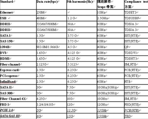
Taking the high-speed computer bus test as an example, the following table lists Tektronix solutions, most of which are recommended by standard specifications. It is worth noting that only Tektronix DPO70000 series real-time digital phosphor oscilloscopes can cover all the bandwidth required by standard compliance testing:
In addition, in the verification of communication specifications, Tek's Pinpoint trigger system provides communication-related triggers. It uses a hardware clock recovery circuit to recover the embedded clock of high-speed serial data, so that an equivalent eye diagram test can be performed. The Tektronix oscilloscope is also the only real-time oscilloscope in the industry that can implement standard equivalent eye diagram testing.
Air conditioning appliances, automatic control system is commonly used in the device, generally used to switch on and off the circuit, is an important component of automatic control and remote control circuit.
Air Conditioning Relay,Air Conditioning Time Delay Relay,Household Fan Air Conditioning Relay,Energy Efficiency Air Conditioning Relay
Ningbo Xingchuangzhi Electric Appliance Co.,Ltd. , https://www.xingchuangzhi.com