![<?echo $_SERVER['SERVER_NAME'];?>](/template/twentyseventeen/skin/images/header.jpg)
Many medical, process control, and industrial automation applications require precise temperature measurements to achieve their functionality. Resistive temperature detectors (RTDs) are often used as sensing elements in these precise temperature measurements because of their wide temperature measurement range, good linearity, and excellent long-term stability and repeatability. The RTD is a sensing element made of metal that has a predictable resistance over the operating temperature range. The resistance of the RTD sensor can be calculated by injecting a current through the RTD and measuring the voltage. The RTD temperature can then be calculated based on the relationship between RTD resistance and temperature.
This article consists of three parts. Part 1 discusses the principle and advantages of a proportional three-line measurement system. In the second part, we compare the influence of the mismatch of the excitation current source with the effects of other error sources. In section 3, we provide solutions to minimize or mitigate the effects of excitation mismatch.
Pt100 RTD Overview
The Pt100 RTD is a platinum RTD sensor that offers excellent performance over a wide temperature range. Platinum is a precious metal and has the highest resistivity as a commonly used RTD material, enabling small size sensors. RTD sensors made of platinum are sometimes called platinum resistance thermometers or PRTs. The Pt100 RTD has an impedance of 100Ω at 0°C, and a temperature change of 1°C results in approximately 0.385Ω resistance change. When at the limit of the usable temperature range, the resistance is 18.51Ω (at -200°C) or 390.48Ω (at 850°C). Higher value resistive sensors such as Pt1000 or Pt5000 can be used to increase sensitivity and resolution.
The Callendar Van-Dusen (CVD) equation illustrates the relationship between RTD resistance characteristics and temperature (T, in degrees Celsius). When the temperature is positive, the CVD equation is a second-order polynomial, as shown in equation (1). When the temperature is negative, the CVD equation expands to the fourth-order polynomial shown in Equation (2).
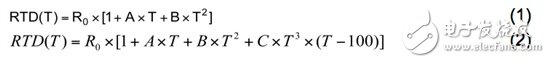
The CVD coefficients (A, B and C) are specified in the European IEC-60751 standard. Equation (3) shows these coefficient values. R0 is the resistance of the RTD at 0°C.

Figure 1 plots the change in Pt100 RTD resistance when the temperature was increased from -200°C to 850°C.
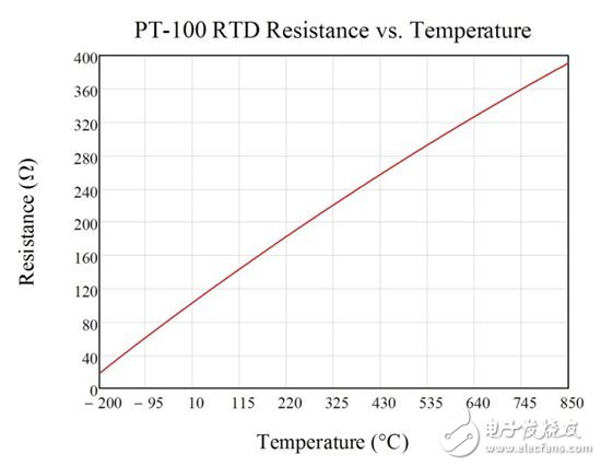
Figure 1: Pt100 RTD Resistance at a Temperature Increase from -200°C to 850°C
Three-wire RTD
Three-wire RTD configurations are very popular because they strike a balance between cost and accuracy. In the proposed three-wire configuration, an excitation current (I1) can generate a voltage potential across the RTD element. At the same time, another magnetizing current (I2) is injected to offset the RTD lead resistance (RLEAD) from the final measurement as shown in Figure 2 and Equation (4-7).
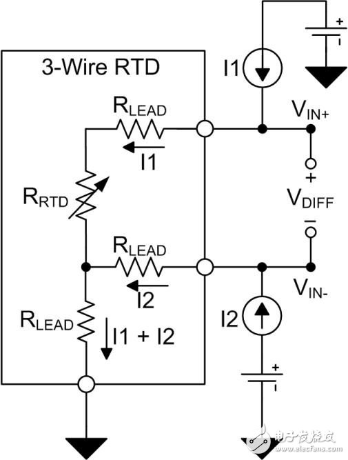
Figure 2: Three-wire RTD with lead resistance

RTD measurement circuit configuration
The differential RTD voltage VDIFF is typically converted by an analog-to-digital converter (ADC) and transmitted to the processor for interpretation. The ADC compares the input voltage with the reference voltage VREF to produce a digital output. Figure 3 shows a three-wire RTD measurement circuit using a discrete external reference voltage. Equation (8) defines the final conversion result based on the total number of digital codes, the resistance of the RTD, the magnitude of the excitation current, and the reference voltage. This example assumes that the ADC has a full-scale range of ±VREF. As shown in the figure, errors due to the magnitude of reference voltage and excitation current, noise, and temperature drift can directly lead to conversion errors.

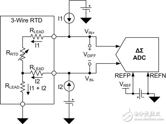
Figure 3: Three-wire RTD circuit with external reference
Place the RTD and ADC in a proportional configuration (Figure 4) to obtain a more accurate circuit configuration for a three-wire RTD system. In a proportional configuration, the magnetizing current flowing through the RTD can be returned to ground through the low-side reference resistor RREF. The voltage potential VREF formed across RREF is provided to the ADC's positive and negative reference pins (REFP and REFN).
The voltage drop across the RTD and RREF resistors is due to the same excitation current (Equation 9 and Equation 10). Therefore, the excitation current changes at the same time reflected in the RTD differential voltage and reference voltage. Since the ADC output code represents the relationship between the input voltage and the reference voltage, the final conversion result can be scaled to the ratio of the RTD resistance and the RREF resistance, not depending on the value of the reference voltage or field current (Equation 11). Therefore, if the excitation current is perfectly matched without affecting the final conversion result, the error due to the magnitude of the excitation current, temperature drift, and noise can be eliminated. In addition, the proportional configuration also helps to reduce the effect of external noise (which seems to be common with input voltage and reference voltage) because this noise is also eliminated.
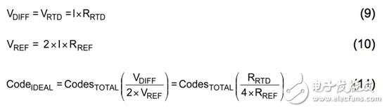
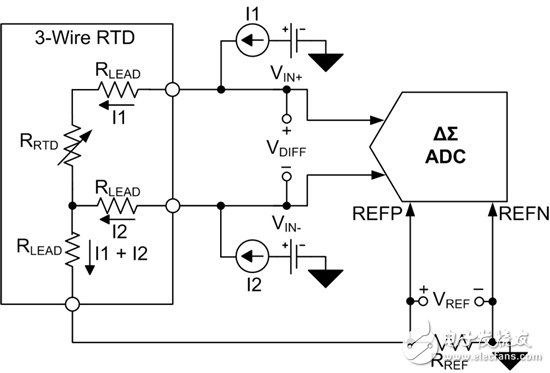
Figure 4: Proportional three-wire RTD circuit
Excitation current source mismatch error
The two field currents must be equal to each other to achieve the ideal transfer function (Equation 11). Magnetizing current mismatch changes the ideal system transfer function because it reduces the effectiveness of lead resistance cancellation.
When a field current is reduced or increased to the limit specified by the mismatch specification, it will have the most severe effect on the transfer function. This is explained in equation (12) where Δ represents the magnetizing current mismatch.
The mismatch in I2 leads to a change in the ideal transfer function (Equation 13).

By comparing the calculation result of Equation (13) with the ideal transfer function of Equation (11), Equation (14) can calculate the gain error caused by the mismatch of field current.

If it is clearly stated that the excitation current mismatch is expressed by %FSR, the gain error can be calculated as shown in Equation (15).

The gain error due to field current mismatch can be eliminated by standard gain calibration. However, magnetizing current mismatch often drifts with changes in temperature, which requires complex calibrations to correct.
to sum up
In the first part of this article, we introduced the benefits of three-wire RTD, lead wire resistance cancellation, and the construction of a proportional three-wire RTD system. We pointed out that when the proportional RTD configuration eliminates the error from the initial accuracy of the excitation current, the mismatch between these two excitation currents still causes a gain error.
Welcome to work with us to turn our attention to the second part of this article – in this section we will provide an analysis of a modern proportional three-wire RTD measurement system to illustrate the sources of error, including the effects of field current mismatch and drift.
Dual Band Router Module,Dual Band Wifi Module,Dual Band Router Embedded Wifi Module,Gigabit Ethernet Router Module
Shenzhen MovingComm Technology Co., Ltd. , https://www.movingcommiot.com