![<?echo $_SERVER['SERVER_NAME'];?>](/template/twentyseventeen/skin/images/header.jpg)
In modern microwave wireless communication systems, passive components such as filters and duplexers play an important role. If traditional metal waveguides, microstrip lines or coplanar waveguides are used for design, it is not expensive or difficult to achieve the required specifications. On the other hand, with the rapid development of microwave and millimeter wave integrated circuits, these conventional microwave circuit structures have been unable to meet the requirements of modern wireless communication for miniaturization and integration of microwave components. Substrate Integrated Waveguide (Substrate Integrated Waveguide) is a waveguide-like structure realized by periodic metal vias. It inherits the excellent characteristics of high quality factor and high power capacity of traditional waveguide devices and is widely used in the design of various microwave and millimeter wave devices. At the same time, the substrate integrated waveguide also has the advantages of easy processing, low cost and easy integration.
In order to generate the transmission zero point, many current filters are designed in the form of cross-coupling. Compared with the pole extraction technique, the advantages are mainly reflected in the controllability of the attenuation pole frequency, simplifying the structure of the filter and reducing the complexity of the structure. Sensitivity, and reduces the difficulty of filter tuning and processing. In this paper, a novel structure of the substrate integrated waveguide double passband filter is proposed by using the pole extraction technique and the coupling matrix method. The filter uses a single cavity to extract the attenuation pole, and uses a filter structure to achieve the double-passband response. The simulation results show that the two passbands form a high isolation, and the return loss in the passband is small. The filter cavity uses a triangular SIW resonator, and the whole filter forms a hexagon, which is compact and effectively reduces the size of the filter.
2 equivalent circuit analysisTaking a six-cavity filter as an example, the equivalent circuit is shown in Figure 1. The second cavity and the sixth cavity are used as the absorption loop to extract the attenuation pole. The position of the attenuation pole is the position of the second and sixth cavity resonances, so the attenuation pole is The position can be arbitrarily determined, which makes the application of the pole extraction technology very flexible. With one filter structure, two different response types of filters can be realized: First, the attenuation pole is outside the passband and can be designed. A bandpass filter with a transmission zero is added out-of-band to enhance out-of-band rejection. Second, an attenuation pole is inside the passband, and a dual-passband filter can be designed. The first, third, fourth and fifth chambers of the filter proposed in this paper form a band-pass filter structure, and the attenuation poles of the second and sixth cavity extractions are inside the pass band, thereby forming a double-pass band structure.
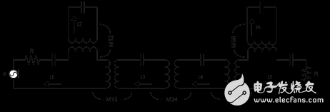
Figure 1 Double pass filter equivalent circuit
In order to verify the feasibility of the design method, a two-passband filter was designed. The design specifications are: the two passbands are 9.6-9.85 GHz and 10.15-10.4 GHz, the passband insertion loss is less than 0.5 dB, the return loss is less than -15 dB, and the two-passband isolation is less than -20 dB. The principle circuit is shown in Figure 1. The coupling coefficient and external Q value between the cavities were calculated by the method given in [7]. The data is as follows. The circuit-level simulation was performed in a microwave office. The results are shown in Figure 2. The expected waveform was obtained, which verifies the feasibility of the design method.


3.1 Study of triangular SIW cavity
Compared with the rectangular SIW cavity, the equilateral triangle SIW cavity has its own characteristics and properties. The filter proposed in this paper is composed of six resonators, which is different from the rectangular SIW cavity. The filter described in this paper uses an equilateral triangle SIW cavity. The space ratio is significantly reduced, and the space is effectively utilized, and the miniaturization of the filter is realized.
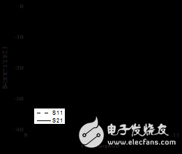
Figure 2 circuit level simulation results
The magnetic field distribution of the equilateral triangle SIW cavity is shown in Figure 3. The magnetic field is a closed curve around the center of the triangle. The formula for calculating the resonant frequency of the square and circular SIW cavity main modes is given in [9], and the equilateral triangle SIW cavity main mode frequency table can be obtained by equation (1):
 (1)
(1)
In formula (1), F is the resonant frequency of the main cavity of the triangular cavity, and c is the speed of light in the vacuum.  For the relative dielectric constant of the medium, L is the side length of the equilateral triangle.
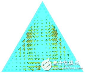
Fig.3 Magnetic field distribution of equilateral triangle SIW cavity
To verify the calculation formula, we selected a set of equilateral triangle SIW cavities with different side lengths for testing. Table 1 compares the frequency obtained by applying Equation (1) with the frequency obtained by applying the CST MICROWAVE STUDIO simulation. The results show that the frequency calculated by the formula agrees well with the simulated frequency, and the correctness of the calculation formula of the main mode frequency of the equilateral triangle SIW cavity is verified.
Table 1
L/mm  / GHz
/ GHz  /GHz
/GHz
1022.5722.56
2011.2911.11
307.527.25
3.2 Filter Simulation and Test Results

Figure 4 filter structure diagram
Table 2 Physical structure size of the filter (unit: mm)
a2.76S134.9
b3.16S344.95
c1.8L120.05
d4.8L221.22
S124.3L320.45
In order to verify the effectiveness of the design method, an x-band substrate integrated waveguide dual passband filter was designed. A dielectric plate having a relative dielectric constant of 2.65 and a thickness of 1 mm was used, the metal through-hole diameter was 0.5 mm, and the hole pitch was 1 mm. FIG. 4 is a filter structure diagram. Where a is the 50 ohm conduction band width, b, c, d determine the external Q value of the filter, L1, L2, L3 are the side lengths of the first, second and third cavity, respectively, determining the resonant frequency of each cavity, S12 S13 and S34 are the sizes of the adjacent two-cavity coupling holes, respectively, and determine the strength of the coupling between the two adjacent cavities. Finally, after the CST MICROWAVE STUDIO simulation optimization, the physical size of the filter can be obtained. As shown in Table 2, the filter structure is bilaterally symmetric. The simulation results are shown in Figure 5.
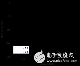
Figure 5 CST simulation results
4 ConclusionIn this paper, a novel substrate integrated waveguide double passband filter is proposed and the specific design steps are given. The characteristics of the equilateral triangle SIW cavity are studied emphatically. The calculation formula of the main mode frequency of the equilateral triangle SIW cavity is given. The simulation results verify that the calculation result is more accurate. A double-passband filter based on a triangular SIW cavity is simulated. The filter has a high isolation between the two passbands, with a small insertion loss and good simulation results. The filter is compact in structure, effectively utilizes space, and realizes miniaturization of the filter.
ZGAR TWISTER Disposable
ZGAR electronic cigarette uses high-tech R&D, food grade disposable pod device and high-quality raw material. All package designs are Original IP. Our designer team is from Hong Kong. We have very high requirements for product quality, flavors taste and packaging design. The E-liquid is imported, materials are food grade, and assembly plant is medical-grade dust-free workshops.
Our products include disposable e-cigarettes, rechargeable e-cigarettes, rechargreable disposable vape pen, and various of flavors of cigarette cartridges. From 600puffs to 5000puffs, ZGAR bar Disposable offer high-tech R&D, E-cigarette improves battery capacity, We offer various of flavors and support customization. And printing designs can be customized. We have our own professional team and competitive quotations for any OEM or ODM works.
We supply OEM rechargeable disposable vape pen,OEM disposable electronic cigarette,ODM disposable vape pen,ODM disposable electronic cigarette,OEM/ODM vape pen e-cigarette,OEM/ODM atomizer device.


Disposable E-cigarette, ODM disposable electronic cigarette, vape pen atomizer , Device E-cig, OEM disposable electronic cigarette
ZGAR INTERNATIONAL(HK)CO., LIMITED , https://www.zgarvapepen.com