![<?echo $_SERVER['SERVER_NAME'];?>](/template/twentyseventeen/skin/images/header.jpg)
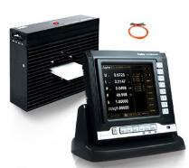
**Introduction to the Inverter**
An inverter, also known as a frequency converter, is primarily divided into two types: voltage-source and current-source inverters. The voltage-source inverter converts DC power from a voltage source into AC power, with the DC link filtered by a capacitor. The output voltage waveform is a rectangular wave that approximates a sine wave. These inverters typically use deep negative feedback for stable operation.
On the other hand, the current-source inverter converts DC power from a current source into AC power, with the DC link filtered by an inductor. Its output current waveform is a rectangular wave that resembles a sine wave. These inverters usually rely on positive feedback, which provides a gain effect.
Most modern frequency converters employ VVVF (Variable Voltage Variable Frequency) or vector control methods. This involves converting the standard AC power supply into DC through a rectifier, and then converting it back into controlled AC power for the motor. However, one disadvantage of VVVF is its relatively low input power factor and high harmonic currents. Additionally, the DC circuit requires large capacitors for energy storage.
The main circuit of an inverter consists of several key components: the power input, a rectifier bridge, a starting resistor, a busbar capacitor, a braking unit (brake resistor), an inverter bridge, and the power output. This circuit serves as the core of the inverter, providing adjustable voltage and frequency to an asynchronous motor. It is composed of three main parts:
1. **Rectifier Circuit**: Converts AC power from the grid into DC power.
2. **Filter Circuit**: Smooths out voltage ripples generated during the conversion process.
3. **Inverter Circuit**: Converts the DC power back into AC power with variable frequency and voltage.
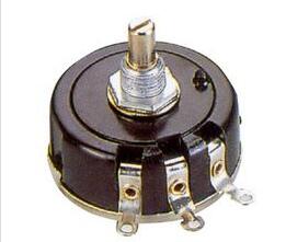
**Potentiometer Introduction**
A potentiometer is a three-terminal variable resistor that allows adjustment of resistance according to a specific rule. It typically consists of a resistive element and a movable contact (wiper). As the wiper moves along the resistive track, the resistance between the terminals changes, allowing for precise control of voltage or current.
Potentiometers can function as either three-terminal or two-terminal devices. When used as a two-terminal device, they act like a variable resistor. They are often referred to as potentiometers because they are used to divide voltage in a circuit, producing an output voltage proportional to the input voltage.
A potentiometer is essentially a variable resistor made up of a resistive body and a sliding or rotating mechanism. By adjusting the position of the moving contact, the voltage between the fixed ends can be varied. This makes them ideal for applications such as volume control in audio systems or brightness adjustment in lighting systems.
The primary function of a potentiometer is to adjust the level of voltage or current in a circuit. It is widely used in electronic devices for controlling signal levels, setting reference voltages, and calibrating sensors.
There are different types of potentiometers based on their construction and characteristics. For example, carbon film, cermet, and wire-wound potentiometers are commonly used. They can also be linear or logarithmic, depending on how the resistance changes with the rotation angle.
Some potentiometers are designed with multiple tapers, making them suitable for specialized applications such as tuning circuits or sensor calibration. Key parameters include resistance value, tolerance, and power rating.
**Inverter Potentiometer Wiring Diagram – External Potentiometer Connection**
When using an external potentiometer with an inverter, it is important to follow the manufacturer’s instructions carefully. In many industrial applications, the inverter is connected to a transmitter or regulator that converts process variables like flow rate, pressure, or temperature into 4–20 mA signals. These signals are then sent to the inverter for frequency control.
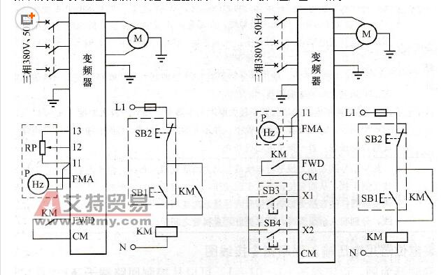
Alternatively, the frequency can be set using an external potentiometer. A typical wiring diagram is shown in Figure 2-18. In this configuration, the inverter's FWD and CM terminals are used for start and stop functions. The manual frequency setting is done via a potentiometer, and the frequency meter displays the set value.
However, using a potentiometer has some limitations. The voltage signal (usually 0–10 V) may be prone to interference over long distances. If the control panel is far from the inverter, signal accuracy may be compromised.
To overcome this, many inverters allow the use of digital frequency-setting inputs, such as X1 and X2, for increasing and decreasing the frequency. This method reduces signal interference and improves reliability.
**External Frequency Setting with Potentiometer**
In Figure 2-18(a), the potentiometer (RP) is used for manual frequency adjustment. The operating panel includes buttons for starting (SB1), stopping (SB2), and adjusting the frequency. The frequency meter (P) is also mounted on the panel.
However, if the distance between the control panel and the inverter is large, it is better to use the digital frequency command inputs. In Figure 2-18(b), X1 is designated as the frequency increase terminal, and X2 as the frequency decrease terminal. Buttons SB3 and SB4 are used to manually adjust the frequency, while the frequency meter shows the current value.
This method is more reliable and less susceptible to electrical noise compared to using a potentiometer directly.
**Precautions for Using the External Potentiometer**
1. The resistance of the potentiometer should not be too high, especially when the control panel is far from the inverter. High resistance can lead to poor signal quality and instability.
2. If the potentiometer is frequently adjusted, ensure that its power rating is sufficient. It is generally recommended to choose a potentiometer with a power rating 5 to 10 times higher than the actual load.
3. Most inverters have internal circuitry that is optimized for specific potentiometer values. Therefore, it is advisable not to use a potentiometer with a resistance higher than 10 kΩ.
4. Avoid adjusting the potentiometer to very low resistance values unless you understand the inverter’s internal design. Too low resistance can cause unnecessary stress on the internal power supply and affect performance.
Since the specifications for external potentiometers vary among different inverter models, it is always best to consult the user manual for detailed connection instructions. Proper setup ensures safe and efficient operation of the system.
solar powered camper trailer,best generator for camper,deep cycle camper battery,battery charger for rv,camper solar battery charger,best battery for a camper
EMoreShare International Trade (Suzhou) Co., Ltd , https://www.emoreshare.com