**Introduction to the Inverter**
An inverter, also known as a frequency converter, is a device used to convert alternating current (AC) into direct current (DC) and then back into AC with variable frequency and voltage. It is commonly used in motor control systems to regulate speed and torque. There are two main types of inverters: voltage-source inverters and current-source inverters.
Voltage-source inverters convert DC from a voltage source into AC, using capacitors for filtering in the DC link. The output voltage waveform is typically a rectangular wave that approximates a sine wave. These inverters usually use deep negative feedback, which helps stabilize the system. On the other hand, current-source inverters convert DC from a current source into AC, using inductors for filtering in the DC link. Their output current waveform is a rectangular wave that resembles a sine wave, and they often employ positive feedback, which provides a gain effect.
Modern inverters mainly use VVVF (Variable Voltage Variable Frequency) or vector control methods. This involves converting the incoming AC power into DC through a rectifier, and then converting it back into controllable AC power for the motor. However, one disadvantage of VVVF is its low input power factor, high harmonic distortion, and the need for large capacitors in the DC circuit.
The main circuit of an inverter consists of several components: the power input, a rectifier bridge, a starting resistor, a busbar capacitor, a braking unit (brake resistor), an inverter bridge, and the power output. This circuit is responsible for providing a regulated and variable-frequency power supply to an asynchronous motor. The main circuit can be divided into three parts:
1. **Rectifier Circuit**: Converts the AC power from the grid into DC power.
2. **Filter Circuit**: Smooths out the voltage ripples generated by the rectifier and inverter.
3. **Inverter Circuit**: Converts the DC power into AC power with adjustable frequency and voltage.
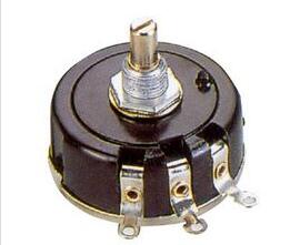
**Potentiometer Introduction**
A potentiometer is a three-terminal electronic component that allows for variable resistance. It typically consists of a resistive element and a movable contact (or wiper) that slides along the element. As the wiper moves, it changes the resistance between the terminals, allowing for adjustment of voltage or current.
Potentiometers can function as either three-terminal devices or two-terminal devices. When used as a two-terminal device, they act like a variable resistor. They are often used in circuits to divide voltage, adjust signal levels, or control current flow.
The basic structure of a potentiometer includes two fixed terminals and a movable contact. By rotating or sliding the control mechanism, the position of the contact changes, altering the resistance between the fixed ends. This change in resistance affects the voltage and current output.
Potentiometers come in various types, such as linear or logarithmic, depending on how the resistance changes with the rotation angle. They are widely used in applications like volume controls, brightness adjustments, and sensor calibration.
Some products require connecting a potentiometer to an inverter to adjust the motor speed or frequency. Proper wiring is essential to ensure accurate control and avoid interference.
**Inverter Potentiometer Wiring Diagram – External Potentiometer Connection**
When using an external potentiometer with an inverter, it's important to follow the manufacturer’s instructions carefully. If the inverter uses closed-loop control, process variables like flow, level, pressure, and temperature must be converted into 4–20 mA signals via a transmitter and sent to the inverter’s input terminals for frequency control.
One common method is to use an external potentiometer for frequency setting. A typical wiring diagram is shown below:
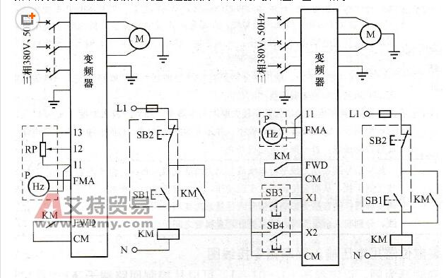
In this configuration, the FWD and CM terminals are used for start and stop operations. The RP potentiometer adjusts the frequency manually, while P is a frequency meter.
However, using a potentiometer has limitations. For example, the input signal is usually a 0–10 V voltage, which can be affected by interference over long distances. To overcome this, some inverters allow frequency adjustment using digital commands, such as increment and decrement signals on terminals X1 and X2.
In this setup, pressing a button increases or decreases the frequency, offering better noise immunity than a traditional potentiometer. The operating column, which contains the buttons and meters, can be located at the site or in the control room.
**Precautions for Using the External Potentiometer**
1. Avoid using a potentiometer with too high a resistance, especially when the control distance is long, as this may reduce anti-interference capability.
2. Ensure the potentiometer has sufficient power rating, ideally 5–10 times the actual power loss.
3. Most inverters recommend using a potentiometer with a resistance not exceeding 10 kΩ to match internal circuit requirements.
4. Do not set the potentiometer resistance too low, as this can cause excessive noise or instability in the inverter’s internal control system.
Since different inverters have varying specifications for external potentiometers, always refer to the user manual for exact wiring instructions.
EV Home Charger
Our EV home charger is cutting edge EV Charger designed to charge electric vehicles both at residential and commercial locations.
Brief overview:
-
Application: Our EV charger are used to recharge electric vehicles conveniently at home as residential EV chargers, allowing our customers to start their day with a full battery or top up as needed.
-
Type of our electric car charger for home:
-
Level 2 Chargers: Our chargers require a dedicated 240-volt circuit and offer significantly faster charging speeds compared to Level 1 chargers. They are the most common choice for residential EV charging.
-
Connectivity: Our modern home EV charging station come with Bluetooth and Wi-Fi connectivity, allowing users to monitor and control charging remotely through smartphone apps, providing convenience and enables users to take advantage of off-peak electricity rates.
-
Cost: The total cost of our electric car charger can be very competitive with high end quality assurance.
-
Benefits: Our EV Home Chargers offer several advantages, including the convenience of charging at home, cost savings compared to public charging stations, and the ability to start each day with a fully charged battery.
-
Environmental Impact: By charging at home,we can reduce our carbon footprint compared to using fossil fuels. Let's contribute to a cleaner environment together!
Ev Home Charger,Ac Ev Charger,Ev Charging Wall Box,Electric Car Charger
EMoreShare International Trade (Suzhou) Co., Ltd , https://www.emoreshare.com
![<?echo $_SERVER['SERVER_NAME'];?>](/template/twentyseventeen/skin/images/header.jpg)